K5LAD - 50+ Years of Ham Radio Memories
Volume XXXIII
Multiple Switchable Antennas – All via a Single Piece of Coax
or
…………………………have a drink of bias tea
This article is about an electronic circuit call a “Bias Tee” or “Bias-T” and how you can take advantage of this useful circuit. Wikipedia defines it as:
bias tee is a three port
network used for setting the DC bias point of some electronic components without disturbing other
components. The bias tee is a diplexer. The low frequency port is used to set the bias; the high
frequency port passes the radio frequency signals but blocks the biasing levels; the
combined port connects to the device, which sees both the bias and RF. It is called a tee
because the 3 ports are often arranged in the shape of a T.
Over time, I realized that my antenna was not ideal and I hoped to add a better, multi-band antenna to my shack in "Studio B." I obtained a nice Hustler 4-BTV vertical and mounted it just outside the sunroom on the chain-link fence but also wished I had a way to switch between the vertical and the loop. Even better, I thought it would be nice to also have an outdoor VHF and/or UHF antenna to hook onto the FT-817.
My original thought was to have a 2-position switch (relay) outdoors to choose between a couple of antennas. I knew, however, that I would need either two runs of coax or a control cable to switch an outdoor relay between the antennas. I planned to add a 35-100 watt amplifier to the mix so I knew the small coax would be insufficient. I did replace the RG-174 coax with a run of low-loss RG-58 diameter coax but I dared not enlarge the mortar hole any larger than that.
Searching the net for articles on "bias-T" circuits, I felt that this would be my best solution. A bias-T circuit allows the user to forgo the use of a relay control cable but, instead, to run the relay control voltage up through the actual feedline cable, i.e., the coax. To make such a circuit work, the voltage input (on the rig side inside the house) had to be isolated so the voltage could not find it's way back into the radio and the voltage taped off at the voltage output (on the outdoor antenna side) would also need to be isolated. This system keeps the voltage from being shorted to ground on either side. One of the keys to doing this is to place a capacitor between the transceiver's output jack and where the voltage was introduced, then another capacitor between the antenna and where the control voltage is taken off the line. It allows the coax to provide a passage for both the RF and the voltage. A simple circuit drawing might explain it visually.

An additional caution to make this work is to isolate the voltage input and output components from the RF. This is accomplished primarily by the RF chokes since its purpose is to .... well..... choke off the RF.
Searching through the Internet, I discovered that MFJ was already using this system, i.e., selling a product to use this type of circuitry. They had their MFJ-4116, MFJ-4117, and MFJ-4118, which were individual units. To use their product you would need a pair of the units, one for the “gazinta” and one for the “gazouta” voltage. They also have the bias-T circuitry like this built into at least one of their 200 watt antenna tuners; model MFJ-927. I preferred, however, to build something myself.
Continuing to search the Internet, I discovered an article by Phil Salas - AD5X in Texas. Phil has some excellent, smaller projects on his website to solve some of the needs of hams and he also often has written both construction and review articles in CQ Magazine. Phil had an article called “DC Power through your coax” which had basically just what I wanted; a bias-T circuit allowing a control voltage to be impressed on the coax to switch an outside relay on and off.
Searching even further, I discovered that Phil had another,
later article "160-6
Meter Remote Antenna Switch with control through the coax cable” for the
same type circuit but it was the MarkII model (my designation, not his) with some nice
improvements. This new circuit was just what I wanted and I began to collect the
parts, however, before I could get all the pieces I needed, I discovered another circuit
for another bias-T circuit by Alan Bloom - N1AL. His circuit provided a system to
switch not one but two relays in an outside box. This would allow the selection of not two
but four antennas. This was even better for my purpose. Alan’s original article is
titled: Homebrew remote coax
antenna switch”. Alan is the designer and “Chief Upgrader”
of the firmware for the Elecraft P3 panadapter http://www.elecraft.com/news.htm,
which integrates itself so well with the Elecraft K3 transceiver.
I hasten to say that the following article is not anything original. I give full credit to both Phil Salas - AD5X and Alan Bloom - N1AL for their work. I only mixed the two ideas together and have provided some simple constructions tips but I believe it makes for a really nice "extra" for many shacks. This project can be easily replicated and, depending on your parts collection (i.e. “junk box”) this can be build quite inexpensively. The outdoor unit I put together is not weather-proofed but is very weather-resistant.
I would highly recommend that you use the URLs listed in this article and actually read the original articles. If something seems to be missing from this write-up, go back to these articles and you will probably be able to fill in any confusion or unknowns.
Some notes might be in order here.
1. What allows the units to be able to switch multiple antennas rather than only two is the use of a positive DC, a negative DC, or AC as the bias voltage. For this reason, the zener diode used in Phil’s circuit cannot be used since it would limit one of the DC voltages and cause the AC voltage to not be able to accomplish what it wants to do.
2. The Home Depot box listed in Phil’s article was unavailable at my Home Depot so I had to replace what he listed with what I could get. They did not recognize some to the numbers given in his article on their computer system.
3. The red LED on the control box only indicates on indoor switch positions 2 and 4 due to the different polarity of the voltage going up the line in position 3 and lack of any voltage in position 1 (no voltage so no relays energized). I thought this was sufficient because the red LED only lets me know that the fuse had not blown. No red indication in any position lets me know that I need to check the fuse.
4. The relays I used happened to be 4 pole double throw (4PDT) but that was overkill if this project is being duplicated. I bought a bunch of these relays at a hamfest for $1 each so I just paralleled the contacts with a heavy wire. This is certainly not required and I would have used a DPDT relay if that’s what had been available. The contacts are adequate for powers at least up to 200 watts.
5. For purposes of identification, the switch positions and ports are identified:
Position 1 = Port #0, Position 2 = Port #1,
Position 3 = Port #2, Position 4 = Port #3
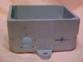
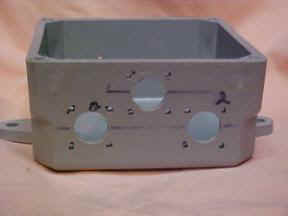
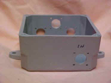
6. The holes for the SO-239 coaxial sockets were drilled using Greenlee 5/8” chassis punches, which made nice clean holes for the sockets. If a chassis punch is not available, then the holes can be made using any good hole-drilling bit. The gray plastic material used for the outdoor box is much easier to drill than a metal box. I mounted the SO-239s on the outside of the box because the gray box is fairly thick and mounting them as you might ordinarily mount sockets on the inside might not leave enough threads showing to make a good, solid threaded connection.
7. Relay information:
------------------------------------------------------------------
Relay #1 (shown on the right in the schematic):
Chooses whether RF input goes to the Relay #1’s choices of ports #0 and #1 or
ports #2 or #3.
If relay is de-energized, the choice is #0 or #1.
If relay is energized, the choice is #2 or #3.
Power leads to Relay 1 are colored green and purple. (only on my unit – use what you have available)
------------------------------------------------------------------
Relay #2 (shown on the left in the schematic):
Chooses which section of Relay #1 has RF connection.
If relay is de-energized, the choice is #0 or #1.
If relay is energized, the choice is #2 or #3.
Power leads to Relay 2 are colored white and orange. (only on my unit – use what you have available)
------------------------------------------------------------------
If power is completely off the outdoor box the unit defaults to the first antenna socket, which is designated as port #0.
Truth Table:
Switch position #1 - Zero voltage - Both relays de-energized -- Antenna 1 (port #0)
Switch position #2 - +12 volts - Relay 1 (on) -- Relay 2 (off) -- Antenna 2 (port #1)
Switch position #3 - -12 volts - Relay 1 (off) -- Relay 2 (on) -- Antenna 3 (port #2)
Switch position #4 - 12 volts AC - Relay 1 (on) -- Relay 2 (on) -- Antenna 4 (port #3)
===============================================================
8. Construction Information
This information should be only a starting place for a constructor. If you use different parts (The Junk box Syndrome) then you can make your own instructions. Parts placement is not particularly critical.
The ASCII drawn pictures that follow are somewhat crude but should provide some idea for where I drilled the particular holes for my outdoor box.
Input SO-239
1 5/8" from top (open) lip ---- 1 " from side
(3) (2) (1) Note: Numbers within brackets designate
_______________________ the SO-239 sockets, i.e., (2) = Ant socket #2
| |
| |
(4)| |
| |
| |
_ | |_
| | | |
|o | |o |
|_ | |_|
| |
| |
| |
| |
| |
|_______________________|
(In)
Top [open]
_______________________
| |
| |
| | ___
| O | |
| | 1 5/8"
|_______________________| __|_
|-1"-|
_______________________
| |
| O |
| | ____
| O O | |
| | 1 3/32"
|______________________| ___|_
|----2 5/32"----| |1 1/16|
|-1 1/16" to lower holes
Top [open]
_______________________
| |
| |
| | _____
| O | |
| | 13/16"
|______________________ _| ___|_
|-1 1/16"-|
==========================================================
Component List (Outdoor unit):
5 - SO-239 coaxial sockets
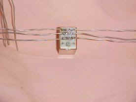
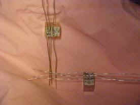
1 - 25 uH RF chokes – these are modified Radio Shack part number #271-102
(See Phil’s second article for modification information – chokes, before modification, are 100 uH)
3 - .1mfd - 500 volt capacitors
1 - .01mfd - 500 volt capacitors
2 - 100 mfd - 25 volt electrolytic capacitors
2 - 12 volt relays (1 DPDT (RY1) and 1 can be SPDT (RY2) or both can be the same)
1
- 1N4744A 15 volt zener diode (not used – see text)
1 - Home Depot box - CAMTEX 5173305 (About 4 1/4" x 4 1/4" x 2 1/4")
3 – 4-terminal terminal strips
Tools needed:
Soldering iron
Drill or drill press
1/16 " drill bit
1/4" drill bit
5/8" chassis punch or means to create 5/8" holes
(Note: Outdoor hardware should be stainless steel if available)
20 - 4/40 x 1/2" screws with 4/40 nuts
5 - 4/40 internal tooth solder lugs
15 - 4/40 internal tooth lock washers
#16 bare wire
Component List (Indoor unit):
2 - SO-239 coaxial sockets
1 - 117v in/12v out 450 ma power transformer – Radio Shack #273-1365
Pri. 120 volt 60 Hz/Sec. 6-0-6 volt .045 amp (Xfmr CT not used)
(about 1 3/4” wide, 1 1/2” deep, 1 1/2” high)
1 - 25 uH RF chokes – these are modified Radio Shack part number #271-102
(See Phil’s second article for modification information – chokes, before modification, are 100 uH)
1 – 1 amp fuse and fuse holder
1 - 4 position, single pole rotary switch
1 – Ten-Tec box – 4 1/4” x 4 1/2” x 3”
1 – Small power diode (low voltage >50volts at low current is sufficient)
2 – ¼ watt resistors for LEDs (1 – 100 ohm, 1 – 300 ohm)
1 – 47 mfd/50 volt cap for green LED circuit (value not critical)
1 – Green LED and mounting hardware
1 – Red LED and mounting hardware
3 – 4-terminal terminal strips
Tools needed:
Soldering iron
Drill or drill press
1/16 " drill bit
1/4" drill bit
5/8" chassis punch or means to create 5/8" holes
(Note: Outdoor hardware should be stainless steel if available)
8 - 4/40 x 1/2" screws and 4/40 nuts
5 - 4/40 internal tooth solder lugs
15 - 4/40 internal tooth lock washers
#16 bare wire
Terminal strips are mounted down 1/2" from open lip.
Reference
articles used:
Remote DC Power through your Coax Cable
Phil Salas – AD5X (ad5x (at) arrl.net)
Low Cost Legal Limit Remote Antenna Switch for 160-6 Meters –
Powered through the coax cable!
by Phil Salas - AD5X
Remote Coaxial Antenna Switch
Alan Bloom – N1AL
http://www.cds1.net/~n1al/ham/ant_switch.htm
Phil Salas provides, on his website, an ever-growing list of helpful hints and useful do-dads for the ham radio person. Many are those forehead slapping ideas that make you want to say, “Why didn’t I think of that?” A full list of the current articles and hints by Phil Salas – AD5X can be found at: http://www.ad5x.com/articles.htm
Highly recommended reading
Alan Bloom’s website, although not a large as Phil’s, has some very interesting pieces and story references. Alan is a masterful designer of clever upgrades and additions to the P3 Panadapter and he, also, seems to have no innovative limitations. It can be found at:
http://n1al.net/ham/index.htm This page was recently moved to new URL
link shown here.
Page updated 05/09/2013 11:42:37 PM