K5LAD's Assorted Ham Stuff
The Dentron AT-3K Antenna Tuner and How to Find Some Usable Documentation
Key search words: Dentron, AT-3K, AT-1K, built like a battleship, AT-3K Operation Manual, AT-3K schematic
I'm guessing that anyone who found this article by searching the Internet did so because they had checked numerous entries about the Dentron AT-3K antenna tuner and failed to find anything useful. This was the position I was in recently when I'd bought a "does not include manual" Dentron AT-3K on ebay and was trying to find some information, or at least a schematic, for this unit. I found several entries where people were also looking for the same thing I was but nobody seemed to be able to locate any. I had one of the units in hand so I set out to "reverse engineer" the one I had, at least to draw a usable schematic. As with several of my website entries, if I have trouble finding information, I figure there's probably several other folks out there in the same boat so I write up the information for myself and store it on my website where I'll know where to find it later and also to make it available for others.
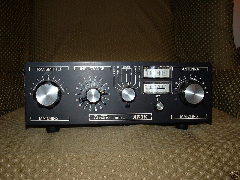
The AT-3K is the budget version of the MT-3000A tuner with information available also on this website. Whereas the MT-3000A has a built in low-power dummy load and a dual wattmeter for reading both forward and reverse power, the AT-3K has a switch position for an external dummy load and dual meters that only to read relative forward and reverse SWR readings from a simple bridge circuit, i.e., not actual power output. The variable capacitors, the tapped inductors, and the inductance selector switch were the same size and type on both units. The MT-3000A has a built in 4:1 high-power balun with rear panel balanced feedline insulators and the AT-3K only has a switch position for balance line (BAL) to feed to an external balun.
Both units are heavily built with heavy chassis and cabinets. The MT-3000A is built like a battleship but the AT-3K is built more like a small destroyer. This is still better than being built like a wooden PT boat. The case size of the AT-3K is a bit smaller than the MT-3000A's case.
The schematic and instruction book for the MT-3000A can be found in numerous sites on the Internet although the printing is usually quite light and difficult to read. That's why I re-did the MT-3000A schematic to make it plenty dark and easily readable and it is available also on this website.
The information, instruction booklet and schematic for the AT-3K, however, seems to have been provided by the authors of the Mission Impossible TV show which self-destructed 5 seconds after providing its information to the user. Even the sites that sold copies of instruction booklets didn't seem to have any.
Dentron also made an AT-1K tuner which was, no doubt, a budget version of one of their other tuners but obviously a popular tuner. The information sheets on this tuner are also very difficult, if not impossible, to find on the Internet. The AT-1K had smaller components and a single meter for SWR readings. I suspect that the information to follow on the AT-3K will be fairly similar to and go a long way toward assisting someone searching for data on the AT-1K.
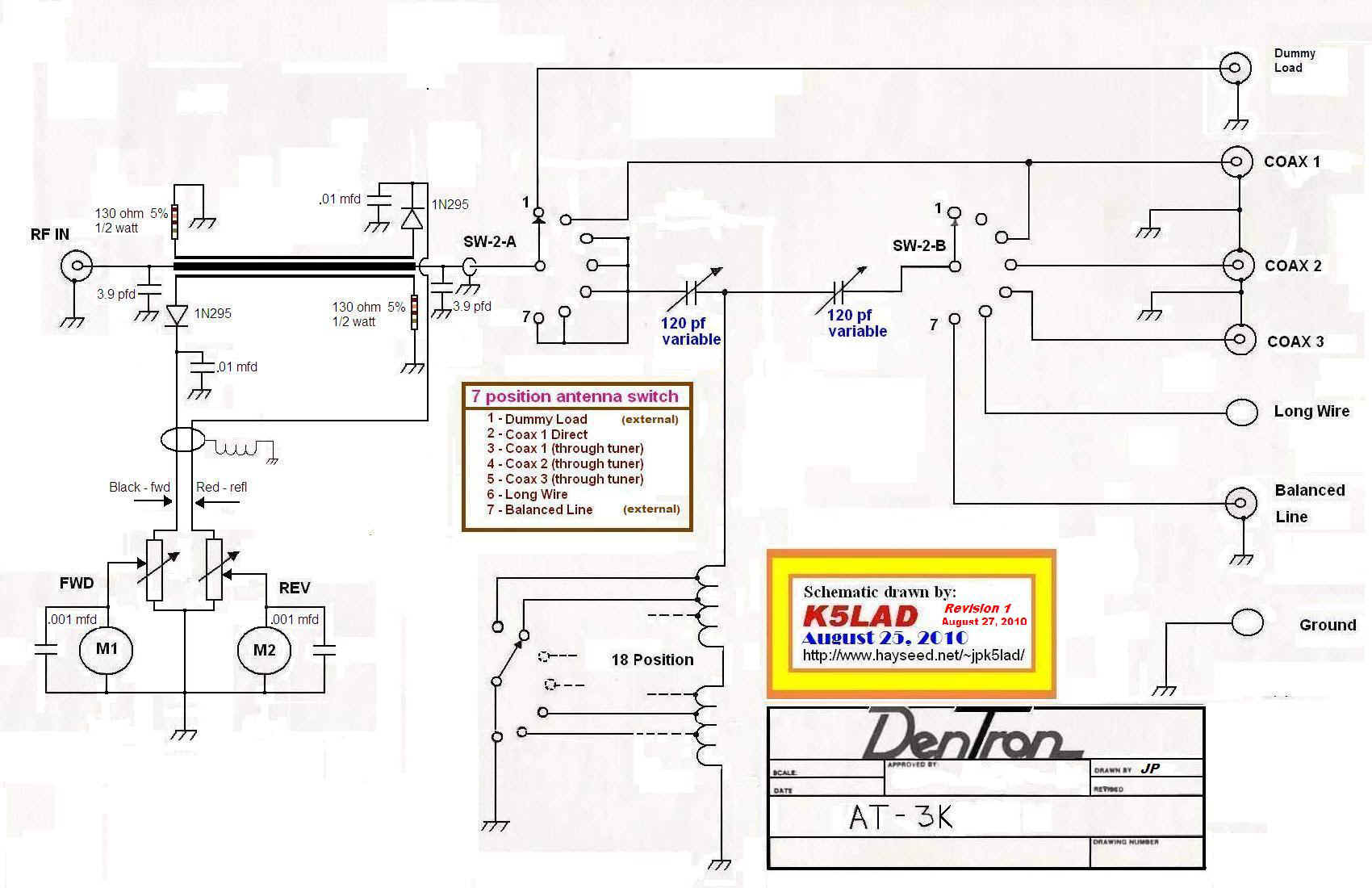
Click on the schematic to view a larger version
You can also click this line to download a file with the schematic
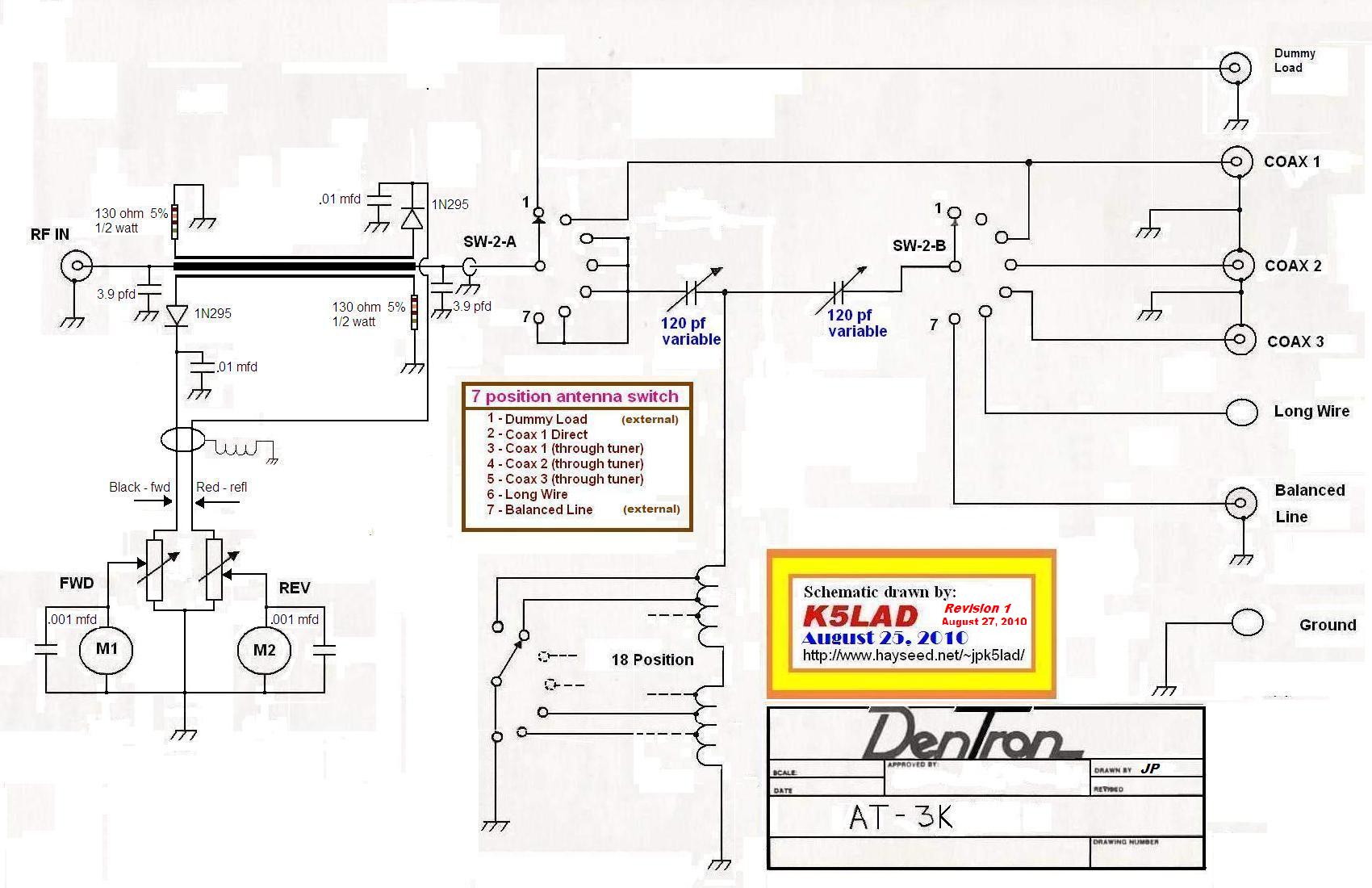
Thanks to sharp-eyed reader Jim Hargrave - W5IFV, there was a small error in the input switch. This revised schematic shows the wire removed between connections for positions 2 and 3 and the new schematic is labeled Revision 1. If you happened to get it when it was first placed on the website, please check and/or download the revised schematic. Thanks Jim!
The Dentron AT-3K is the conventional T-shaped Transmatch tuner made popular by Lew McCoy - W1ICP (SK). Basically, the power comes into the unit via the antenna Input port, through the SWR Bridge sensor, to the input switch. This switch allows the input power to go from the rear-apron coax port to:
(1) the user's external dummy load,
(2) directly to the antenna plugged in Coax #1 (bypassing the tuner circuit),
or (3) to the Transmitter Matching variable capacitor.
Once through the second variable capacitor, the path is back through another area of the switch which allows the tuner-manipulated power to go to Coax #1, #2, #3, the insulator for a single wire antenna, or to the previously-mentioned coax socket to feed an external balun to connect to a balanced antenna feedline.
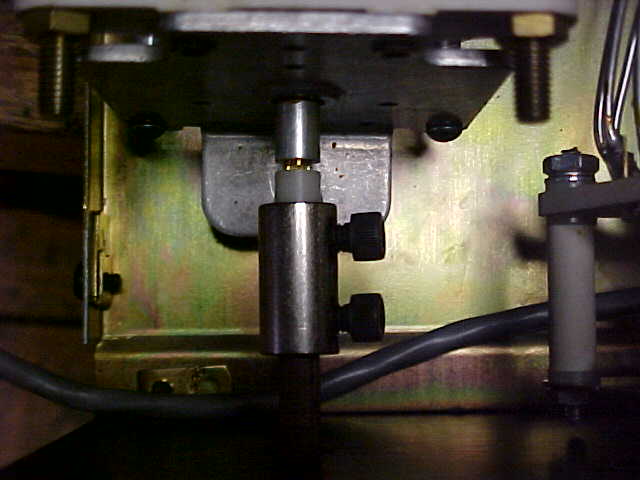
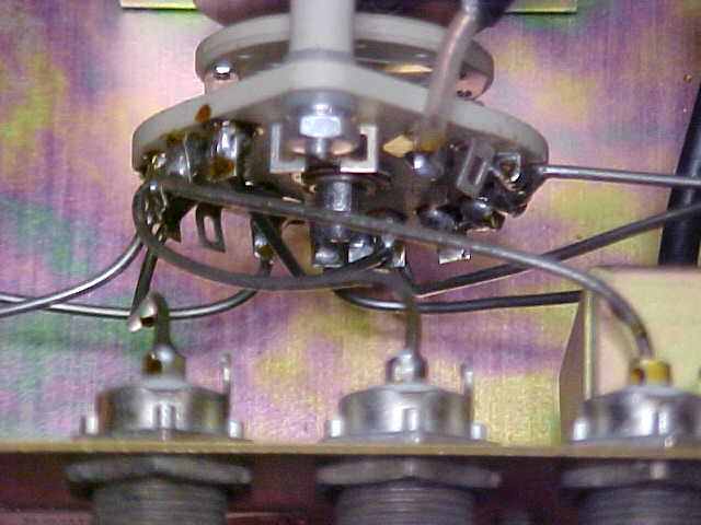
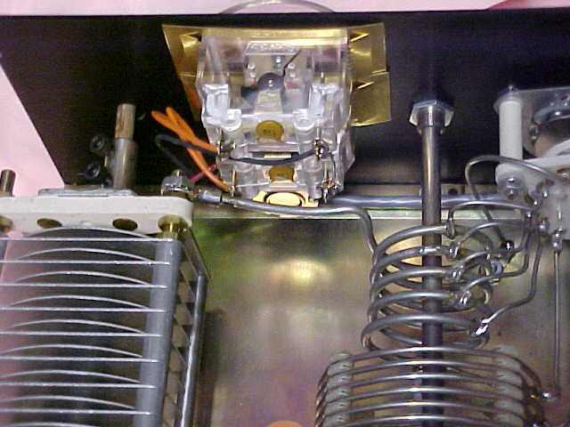
This circuit is shaped like a capital T with the two top horizontal parts made from two series connected variable capacitors and a tapped inductor connected at the junction between the two variables to ground. Obviously, for this to work properly the variable capacitors must be mounted as completely insulated above ground and the the mechnical connection between the variable capacitor shaft and the knob must be insulated and isolated to assure that the user receives no RF burns while tuning. The picture to the left shows the white insulated piece connecting the variable cap shaft to the coupler on one of the front knobs.
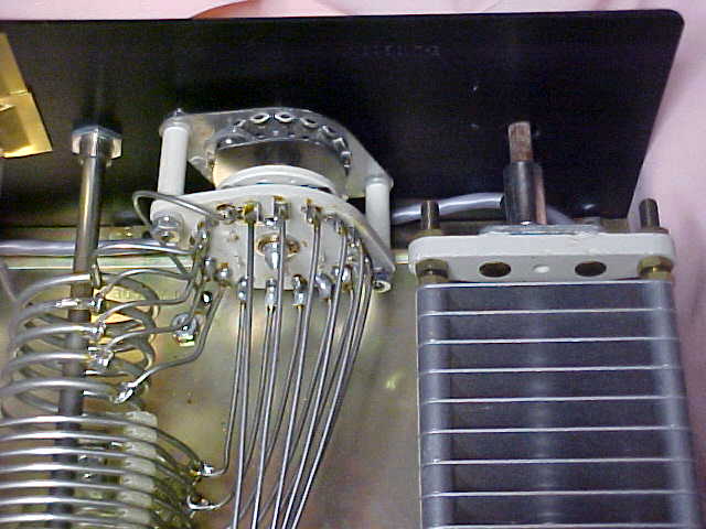
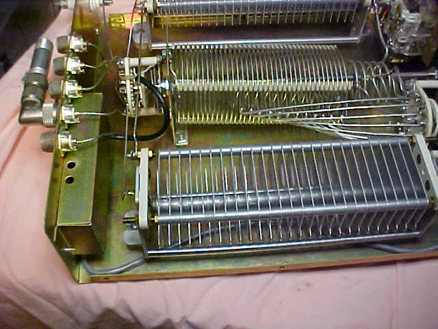
The Inductance selector switch is 18 position and provides taps which should match most antennas from 160 meters through 10 meters. Although the lowest tap (with the least inductance) is very small the size of the variables, even at their minimum capacity, probably will not allow much (if any) tuning on 6 meters.
When I get a new tuner I find that they almost always have the knobs mounted backward to what I like so I generally loosen the knob mounting screws and remount them 180 degrees from their original position. Typically I find knobs at the 0 (zero) position when the variable is fully meshed but I prefer it just the opposite. It makes more sense to me for the knob to indicate zero at minimum capacity and 100 at maximum capacity. The reason I do this is because often, with this type of tuner, I can find several capacitor and inductor positions which show minimum SWR. Typically, however, if several tunings are available with low SWR, the tuning which uses more capacity and less inductance will generally allow the least loss in the tuner and highest output power to the antenna. With my knobs placed pointing to the highest number for the highest capacity, I can remember which tuning to use, i.e., less for me to remember.
When I received my AT-3K tuner, the SWR bridge circuit was not working correctly. Even when I connected the tuner to a load with an obvious SWR, the lower meter (SWR) did not read anything. I checked the meter itself and it was reading an externally-provided voltage correctly, the same as the upper meter. Since it was difficult to remove the cover protecting the SWR bridge circuit I had planned to just represent the circuit on my "reverse engineering" schematic as a box. To remove it required unsoldering a bunch of stuff to get to it but with the SWR part of the circuit not working, I had to unsolder and remove it anyway. At least it allowed me to take some pictures to share and to get most of the component values to complete that part of the schematic.
I assumed that the problem was caused by an open diode feeding the lower meter but when I got the PC board out and measured the components, the diode was not open. Ultimated the steps which led to the fix were to resolder all the connections on the small SWR bridge board, even though they all looked good. I guess the lesson to be learned was, when in doubt............ resolder.
These pictures show the SWR bridge PC board removed from the chassis and cover. This will allow you to see the RF choke which was not identified with a value.
The circuit used was a simple RF pickup unit found in many circuits from the 1950s-80s. This type of pickup is somewhat frequency sensitive and requires much more power on 160, 80, etc. to read full scale. On the higher frequencies, only a few watts can pin the meter.
Also, the alert reader might notice that the center conductor on the coax piece is loose and not soldered in place on the sensor strip. It had actually broken free while I was removing the board and it was easer to manipulate it for pictures with the lead free. The center lead was resoldered in place before re-assembling the unit.
On the AT-3K schematic, I've identified all the values that I could. A few were not marked with a particular value so I had to leave them without a known value. The RF choke on the SWR bridge had no markings and I was unable to find a similar circuit for any other Dentron product so that one is a guess. The dual potentiometer on the front panel was not marked and I was unable to get a good reading on it. Usually pots in a similar circuit are around 25 to 100K each but I kept coming up with a much lower value, something like 3.5K for both. The primary thing is, if you're replacing this dual pot is, both pots should be the same value and should have a linear taper.
If I had a choice between the Dentron AT-3K and the Dentron MT-3000A, and prices were close or no object, I'd always go for the MT-3000A. If, however, I was trying to find a full power tuner but spend as little as possible, then the AT-3K would be very much in the running. And if you can find a tuner but cannot locate the documentation and/or schematic for it, then a quick click on this will get you a copy.
I hope this has been helpful to you. Enjoy!Click on any of the pictures below for a larger image:
Antenna Selector switch
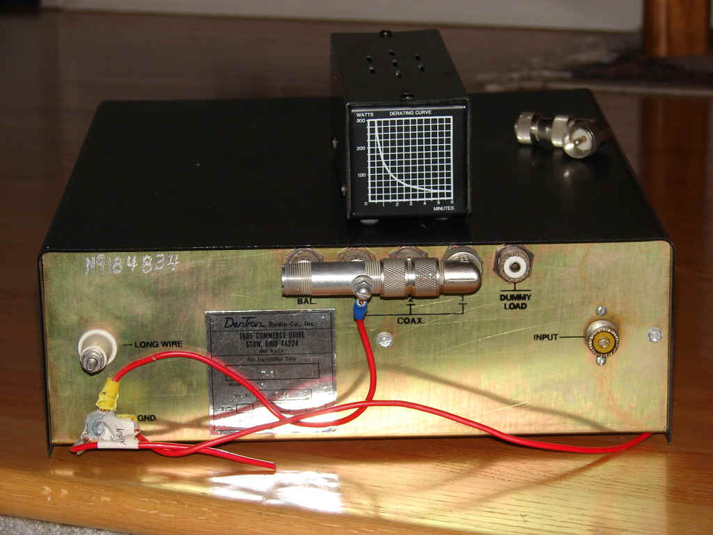
Rear cabinet view
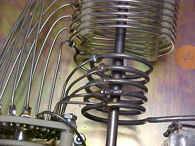
Inductance Selector switch
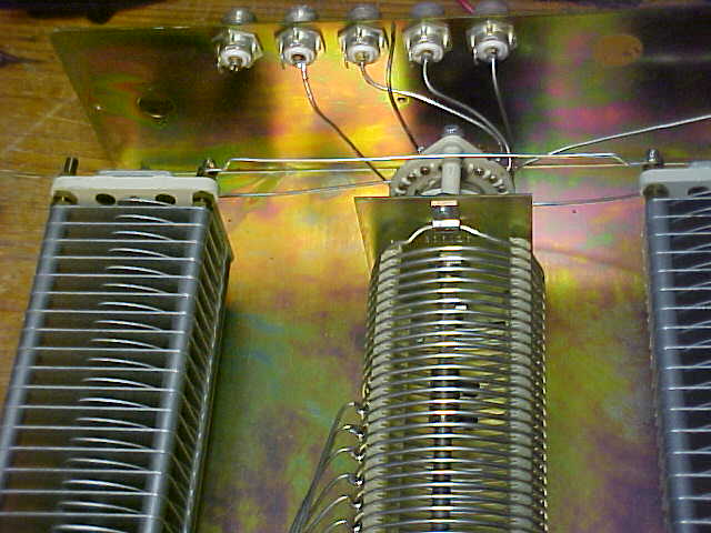
Tuner Inductance Parts
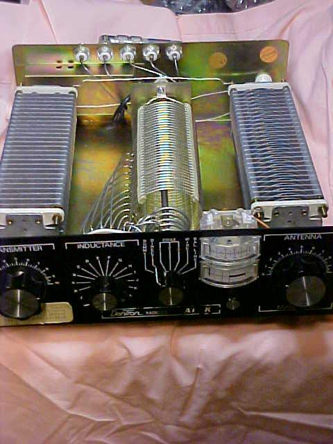
Interior view from the front
Rear view of tuner interior
NOTE: SWR bridge PC board and cover has been removed on the left side
Interior view of meters
Interior showing SWR bridge in place
Smaller inductor
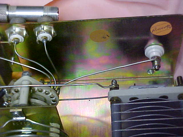
Insulator for single wire antenna
Note: Orange inspection sticker..... I wonder where Annette is now?
If you're also needing the actual operating instructions for the AT-3K tuner, you should be able to download the instructions for other Dentron antenna tuners, or almost any other similar tuner for that matter, and those instructions should be that same as for the AT-3K. This website has a copy of the original MT-3000A manual in the Downloads section.
Created August 25, 2010
Last updated 05/15/2011 23:29:10 PM
Back to K5LAD's Assorted Ham Stuff Menu

