Oh, say, can you see?
Adding a
decent S-Meter Light for the Yaesu FT-736R transceiver
My only criticism of my FT-736R VHF/UHF transceiver was the
poor lighting of the meter. I could just
barely see a glimmer of light in the lower left corner of my meter. Whereas the dial to display the frequency was very
bright and easily readable, the meter lighting was so poor that I could not only not read
the increment marks for values displayed on the meter face, I could not even be sure that
the needle was reading upscale at all.
The meter face reminded me of many of the meters I
had seen with a colorful scale and when lighted from behind, would allow it to be easily
seen and deciphered. The radio was designed
and built in the era when most ham equipment used the small grain of wheat bulbs for dial
and meter illumination. The grain of wheat
lamps were so called because of their small size and absence of an actual base. Instead, the two wires exited one end of the bulb,
which was just barely covered with a small piece of shrink tubing. I thought all this could be improved by replacing
the incandescent grain of wheat bulbs with more up-to-date white LEDs. Since the LED is constructed to have a built-in
lens to direct light to a small spot, I planned to use the standard trick of scuffing up
the sides and front lens to better defuse the light.
One or two of these should do a nice job of shining through the meter face and
illuminate all of the scales quite well.
With that thought in mind I opened up my 736R by removing
the top cover to see what kind of space was available for my new lighting scheme. What a disappointment! The meter case did not have
a transparent or even a translucent back which would allow the normal 'behind the meter'
lighting scheme. In fact, the back of the
meter was a solid black piece. The system
used by the original Yaesu designers was, by far, the worst that could possibly have been
made.
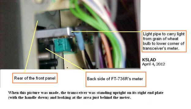
Into each of these holes was a blue-colored rubber 'boot'
with an inner diameter large enough to allow the insertion of one of the two grain of
wheat bulbs. The boot would provide a blue color
filter to bath the meter in a soft blue lighting pattern.
The 'design plan' evidently was to take the small
illumination provided by these two lamps and disperse this light through the plastic
pieces and into the lower corners of the meter face.
Owners of the FT-736R will, no doubt, attest to the fact that this didn't work very
well, in fact, almost not at all, and that was when you still had both of the grain of
wheat bulbs still burning. Show of hands, how
many who own a 736, still have both of those bulbs still working in their unit? Ah ha, I thought so....... me neither.
At first look, I could not see how it could ever be a
suitable system of lighting the meter so I set about to find a good substitute. If only they had provided a translucent back on
that meter, my problem would be solved and the modern day upgrade would have been a
crowning success. Unfortunately, that was
not to be the case.
As an initial test, I took a single bright white LED and
mounted it, along with its dropping resistor, on the end of a parallel wire power cable,
which I terminated in an Anderson PowerPole connector.
I use them in my station to dispense 12 volts DC and have quite a few spots where I
can plug things in like this lighted LED probe. I
thought that possibly, even though the grain of wheat bulbs failed to provide sufficient
light, perhaps the LED could defuse enough light via their plastic 'light pipes' since it
was many times brighter than the original bulbs. I
tried numerous things, placing the LED in every position I could, but even then, the light
on the meter face was far, far insufficient. Even
removing the blue rubber boots did not allow much more LED light to do its job.
I scratched my head for several hours trying to come up
with a Plan B or Plan C. When I finally
reached around my Plan Q and still couldn't come up with anything that didn't require a
major overhaul of the radio's meter or possible unrepairable damage of my meter, I decided
to give it up as a bad idea. I returned the
original blue boots, reinserted the two grain of wheat bulbs (one burning and one burned
out) and put the radio's top cover back in place.
There were several reasons that I chose to light the meter
externally. First, doing the task internally was pretty much a no-go as explained in
the previous paragraphs. In addition to that, although it would not look as nice, an
external lighting scheme should work well and could be quickly removed if the
photographers from CQ Magazine came to take pictures of my shack for their cover.
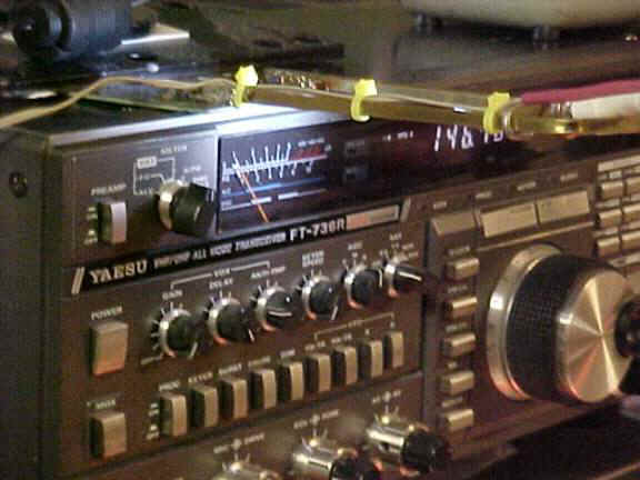
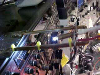
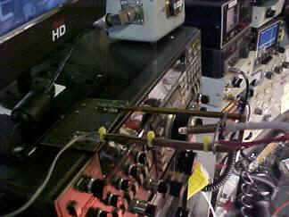
The system I chose to light the meter on my FT-736R is shown here:
The support use was constructed of square brass tubes, the
type often found in hobby shops or well-stocked hardware stores. The particular tubes used here were purchased at
an Ace Hardware store some years ago. The
tubes use were in boxes marked:
K & S Engineering Stock # 173 size
3/16" x 3/16" x 12"
K & S Engineering Stock # 171 size
1/8" x 1/8" x 12"
The smaller square tube (#171) is an exact fit sliding
inside the larger square tube. Although this
was done for strength I did not try it with a single piece. It just seemed like it would
be easier to bend and there would be less chance of the pieces collapsing with one tube
inside the other. The foot-long, double
thickness tube was bent into a square U with each side being 5" long and the center,
connecting piece at 2".
The brass tubing can be easily soldered, enabling its attachment to a piece of printed circuit material which serves as the base. I couldn’t find my unused printed circuit boards at the time so I used an old, unused board that had been etched for some other project and then not used. It was handy, it would never be used for its intended purpose, and it would not show so I used it. This base sits atop the FT-736R, just above the S-Meter. My station organization places my FT-736R above my eye level so I don’t even see the base pc board holding the LED meter lighting apparatus. Anyone attempting to duplicate this accessory can doubtless do a better job and make it far more attractive than I did on this one. Mine, however, was built for utility and not for beauty.
A single bright white LED is used as the lighting source. It has a 330 ohm, 1/8 watt resistor in series with
one lead and is attached to a 12 volt source. I
currently have no switch in the power lead but next time I am inside the 736, I plan to
find a convenient point to attach the power lead so that it will turn on and off with the
transceiver. The LED pulls less than 30 ma of
current so any area supplying 12 volts and is turned on and off with the power switch,
should be adequate.
The LED fits inside a piece of round brass tubing, which is
.28” in diameter and came from the same source as the square tubes. This piece is about 1.5” long and holds both
the LED and the 330 ohm dropping resistor. I
don’t still have the original box for this one so I don’t have the stock number
for it. I have a nice collection of assorted
sized and colored heat shrink tubing that I use on most of my projects and this one was no
different. I used a $10 (on sale) heat gun I
picked up from Harbor Freight and it serves me well.
Now my tubing pieces reflect the color the box said they were rather than all being
colored with black soot from the wooden matches I used to use to shrink them. I highly recommend that if you use shrink tubing
that you invest in one of these HF guns. Your
wife will be glad to get back her hair dryer and you’ll stand less chance of setting
your hamshack on fire.
I used a piece of #12 wire to wrap around the tube holding
the LED and soldered it on. The ends of the
wire were then mechanically wrapped around the square tubes. I’d planned to leave the wires holding the
LED tube free until it was adjusted just right and then solder them to the square rails
but there’s really little adjustment necessary and just a mechanical wrap on each
side holds it securely. I ended up leaving
them unsoldered.
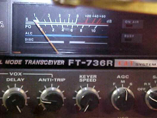
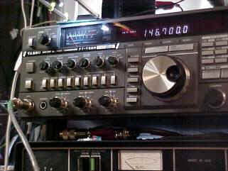
Now, when I look at the meter on my FT-736R I can easily
read the values off the scales. It looks
something like this:
Altogether, it looks something like this on my console:
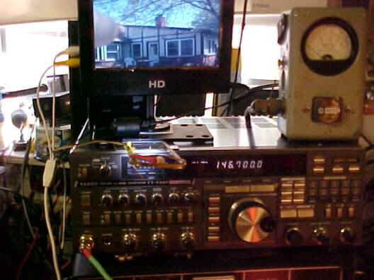
This picture was taken from a standing position so the LED light apparatus does block the meter in this picture but that’s not where I am when I’m operating so it is not a problem. The 7” LCD screen on top (marked HD) is a low cost HDTV/LCD panel that I picked up at Big Lots. I have an inexpensive color TV camera attached to it and it's looking toward the backside of my house.
Other assorted shots:
|
|
The power cable for the LED uses the yellow plastic cable ties to hold to the rails and keep it out of the way. |
A top-down shot showing the rails, the LED mount and a bit of the used printed circuit board on which the rails are soldered. Note that this was prior to cleaning up the workplace --- there really is a green desktop underneath this mess. |
|
|
With the power turned off, the LED is extinguished for, perhaps, a better view of the device. The lens of the LED is about 2” away from the meter’s face. The meter face is nearly unreadable without the LED. |
This angle shows a bit of a glare from the LED but it’s a small price to pay for the convenience of seeing the transceiver’s meter. |

Now, when the Star Spangled Banner music plays in my
hamshack and I hear the singer croon, “Oh, say can you see,” I look up at my
FT-736R and say to myself, “Yes……………… yes I
can………”
Jim - K5LAD
Created
April 4, 2012