Rig Installation
I looked for a long time to determine where I wanted to install the transceivers in this vehicle. The rigs, an Icom IC-7000 and an Alinco DR-610, both had previsions for separating the radio bodies from the control heads. I already had the cables for both radios so that was not a determining factor in where I mounted the transceiver bodies. Many, if not most, vehicles built these days don't really provide adequate space for mounting ham rigs, even though the size of the radios has gotten smaller and smaller. I couldn't actually find a space in the 2007 Tahoe which would support the mounting of these radios, especially if I wanted to maintain adequate cooling around the units.
I also spent much time trying to decide where to mount the two control heads so I could easily the dials and screen and also to have them within an easy reach while driving. I have had various radios mounted previously in several different vehicles and I know now that it is important to have what needs to be seen and changed to be as high a possible. If the driver needs to look at the control head for a even a split second, it is preferable to be able to maintain a good peripheral vision of what is happening around you. Good sense should tell us that we should NEVER look away from the road while aiming a 3000+ pound missile down the highway at 60+ miles an hour, whether to look at a dropped pencil, a CD being loaded, a cell phone dial, or a radio. Since we know this happens daily.......... hourly, we must acknowledge that many of us do not use good sense. I wanted to be sure that wherever I mounted the control heads would only be a small amount down from my view of the road.
The Tahoe, as with many newer vehicles, don't offer too many places for mounting the control heads which conform to the limits listed above. I temporarily mounted the 7000's control head and a dual needle SWR/power meter on a piece of thin aluminum sheet and laid it on the top of the dash. I held it in place with a couple of thin aluminum strips which looped through the windshield defogger outlet on top of the dash. I also placed an old mouse pad between the aluminum sheet and the top of the dash. This worked OK and held things in place but the power meter required two extra coax cables plus the mike cable and the interconnecting cable on the 7000's control head and I didn't like all the wires. It also didn't look good so I looked for a more permanent location.
I finally chose to mount the actual radios on the floor space immediately below the center of the dashboard, mounted on a piece of pine board with a couple of 90 degree aluminum angle pieces to hold the board secure to the vehicle's carpet. The control heads were mounted on a 12" piece of aluminum angle stock which had been formed to fit the curved piece of dash between the center air conditioner outlets and the radio/CD equipment.
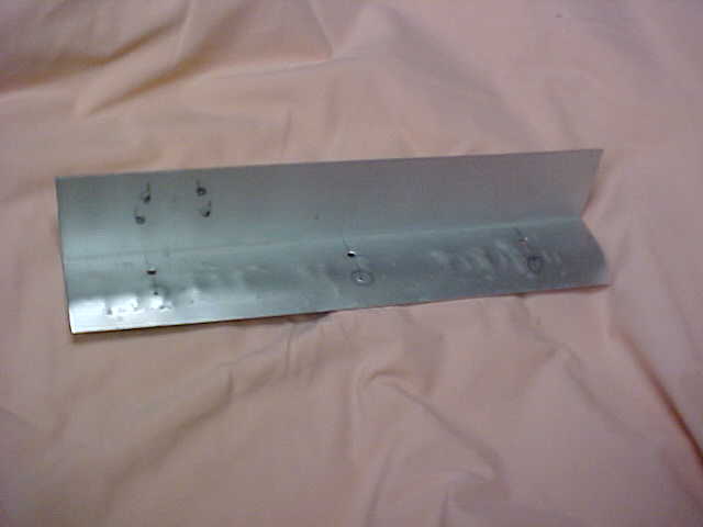
This picture shows the aluminum piece which was originally part of a aluminum angle stock purchased at Home Depot. The stock measures 2" by 2" and is 1/16" thick. Because the Tahoe's dash where this piece was to be attached, is curved, I formed one side of the angle stock into a curve. This was done by hammering the piece on a 2" pipe held in a large bench vice. The picture above shows some of the results of that hammering and it's not a particularly neat result but it serves the purpose quite well.
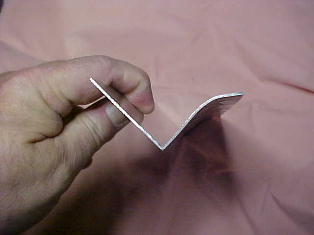
This picture shows the resulted curvature of the piece. This aluminum stock is not soft and easily pliable as most aluminum pieces are but it is quite stiff and not easily bendable. To add this curvature does require some effort and care but the bracket made is quite nice and sturdy and holds the control heads very steadily.
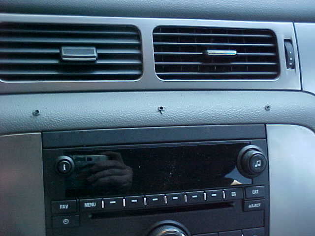
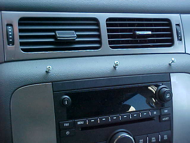
The pictures above show the area where the formed aluminum bracket it mounted to the dash. I was originally hesitant about drilling this area as I did not know what might be immediately behind it. I used a small battery-operated Dremel-type drill with a very very small bit. The holes drilled were so small that if that area had proven to be non-usable, my wife would really not even be able to see these holes in her new vehicle. Once I had the small holes I used a piece of wire (about #28 sized) and probed around to see what I might hit and how close it was. As fortune would have it, there seems to be a lot of available space behind that area so I convinced myself that I wouldn't be hitting anything that could cause a problem. I was originally planning to drill out the holes and insert expansion screw holders (like Molly screws) to solidly hold the bracket but I could see that the material was heavy enough that the three #8 sheet metal screws would work fine.
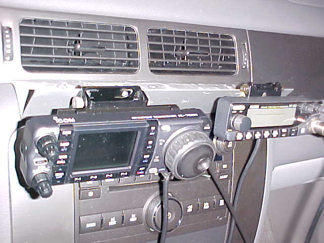
Here's what it all looks like with the control heads mounted on the aluminum bracket. I must admit that I failed to take into consideration the travel of the automatic transmission shift lever and it bumps the IC-7000's control head when I try to go into a forward gear. For now, until I can get that fixed, I plan to drive everywhere in reverse. Actually I'll get that fixed and take another picture. My advice, if you're installing your mobile setup...................... plan, organize, check........... then do it all again.......and again................and again..........
When the installation is complete, and the IC-7000 control head moved further to the right, I'll be able to adjust it upward to allow me to look directly at the screen and all the knobs and buttons. Right now, it's pushed down to allow the gear shift lever to move through its entire travel. After all, the actual movement of the vehicle is the primary function............... but mobiling is a very close second.
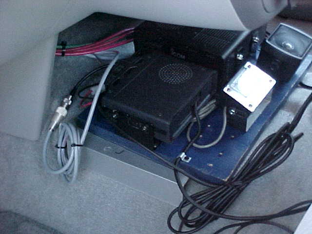
This picture shows the pine board to which I attached the mobile mounts for two transceivers. The picture is taken from the driver's side and shows the board's location atop the transmission hump and directly below the center console of the dashboard. The aluminum piece shown and a duplicate on the other side, hold the transceiver mounting board to the floor. It is not physically attached but with the cables and the grip of the aluminum pieces, it does not move.
Also shown is the external, upward firing speaker plugged into the IC-7000. The regular speaker would probably be nearly as good but I liked the ability to aim it directly where I wanted the sound. To the left of the speaker is a dual-needle meter attached to the SWR/power meter module I built -- more information on this later. The cluster of red and green cables make up the power cables coming through the firewall and are shown terminated in another picture. The surplus black cable is the interconnection cable between the transceiver and the control head. Unfortunately, when the transceiver is not mounted far back in the vehicle, there is surplus cable to deal with. I may later find a place under the seat to "store" the surplus.
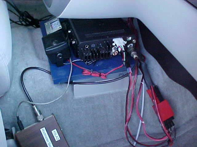
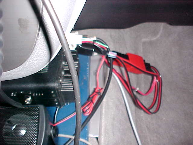
This is not the neatest installation but I wanted to have some flexibility in how I used the power connection so this is how I ended up. The two heavy #8 red +12 volt cables and the #4 green -12 volt cable are terminated in a 75 amp PowerPole connector which plugs into a large PowerPole adapter. This adapter, shown on the right-hand side of the pictures above, take a 75 amp connection with 4 - 30 amp sized connectors coming from it. Currently the cable to the IC-7000 and a small PowerPole connector taking power to the screwdriver antenna are connected here. The single #8 red wire and a connection to the #4 green ground wire connect to the VHF/UHF transceiver. If I had children often riding in the front seat of the vehicle, I probably would have chosen a neater and less obvious power connection but this is a "retiree's vehicle" and we don't move our feet very quickly for anything and especially inside the vehicle.
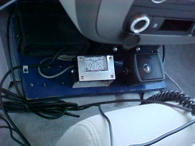
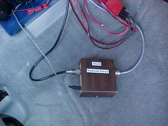
The picture on the left is looking down on the transceiver mounting board and does show the dual-needle meter. When I had my temporary setup on top of the dash, I found that the dual-needle meter was excellent for tuning the screwdriver but I was using a Daiwa meter which was larger and required two coax cables to run up to it. This was just too much so I chose to go a different route. I built my own power meter but with the sensor and electronics in a separate box (right-hand picture) and only a small single cable going to the meter. This keeps the coax down low (around our slow-moving feet) and out of the way. This has worked out very well and I'm very pleased with the result and so is the wife. The dual-needle meter was purchased from MFJ probably 10 years ago and used for another project. It does have one or two 12volt bulbs behind the dial to illuminate the meter so I picked off some 12 volts from the IC-7000. When I turn on the 7000, this meter light comes on and when the 7000 is turned off, the meter light goes off.
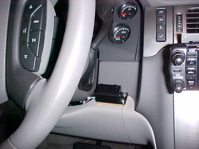
This is where I chose to mount the raise/lower switch for the Little Tarheel screwdriver antenna. It's a very convenient spot and works just like I had hoped it would work. The switch, which comes with the Little Tarheel, is mounted with a couple of screws to a piece of cork about 1/4" thick which was purchased from Lowe's for another forgotten project. The cork has some double-faced tape on the bottom which sticks securely to the dash material. With the antenna mounted where it is, I can easily see where the antenna is tuned. I've place white plastic tape strips on the black coil shield and on the strips are the numbers for the bands. I can also use the receiver in the IC-7000 to get close to the right band. The strips also work to remind me to lower the antenna all the way down before taking the Tahoe into the garage.
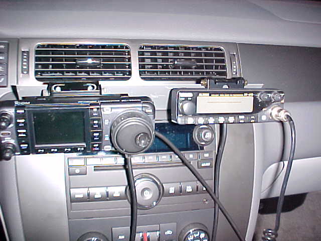
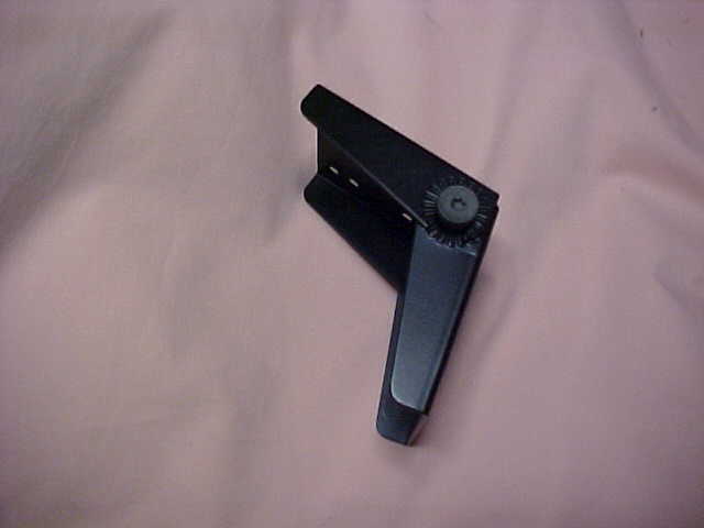
This picture shows the current installation, which will not be the final installation. The bracket used to hold the VHF/UHF control is the one sold for the Alinco DR-610 and is an adjustable clamshell type. The IC-7000's control head has the sliding type of holder which is sold for the Icom IC-7000 and that one is attached to a clamshell type adjustable bracket which I bought years ago at a hamfest. Pictures of this bracket are shown below.
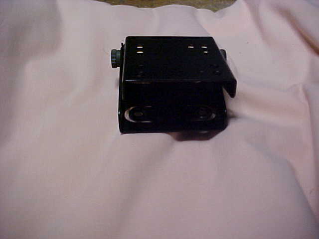
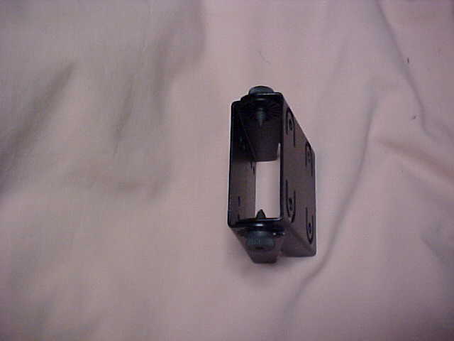
The brackets were brand new and I had no current need for them but they looked like something I might need in later years so I bought several of them. I'm really glad I did since it is perfect for this installation. I don't know what their original use was.
You can almost not see the L-shaped aluminum bracket which holds the control heads to the vehicle's dashboard. I actually haven't come up with a special place to hang up the microphones when they're not in use. Perhaps that will come later but, for now, I just lay them close-by in the seat.
Updated 09/30/07 05:33 PM
Page visited 545 times
