 This
picture shows the power cables entering the hole and grommet.
This
picture shows the power cables entering the hole and grommet.
12 volt Power Installation
I spent several weeks, no, actually several months, trying to decide how I would run the power for my new installation. I already had the cables left over from a previous mobile installation. The red B+ cable was a #8 so I choose to run a double cable for it. The #8 would have handled the rig's current requirements but I always liked to provided plenty of overhead should I decide to add something bigger. It's not as difficult to oversupply current at the initial installation than it is to try to add something at a later date. If I'm going up the hill for water and I only needed a gallon, I'll take a two gallon bucket, just in case more has become available.
The negative cable I had was a #4 so I was quite sure that would handle anything I wanted to put to it. I also ran an extra #8 red cable to provided power to my VHF/UHF transceiver. Those three runs: a. 2 - #8 for +12 v., b. 1 - #8 for +12v., and c. 1 - #4 for -12v. were all fused separately.
I studied the firewall of the Tahoe, searching for a "GM-provided" hole but never could find anything adequate. A local man who had installed several high-powered stereo sound systems said he always just "poked a hole" through the boot surrounding the steering column but he wasn't taking on any more jobs at the time (I realized later that this was to my advantage). Finally, after seeing no easy way for someone of my age and size to get through the firewall, I called a stereo/sound system installer in Tulsa. They had just installed a large stereo in a Tahoe a few days before so I was already encouraged. I made an appointment for several days later and took it in.
The fellow who did the work allowed me to watch and he seemed to know exactly what he was doing. The visions of squirting brake fluid and wild sparks flying soon left me and I watched him as someone might stand back and watch an artist at work. The complete job took just about an hour and cost me $50. Having already studied what I might have to go through with no assurance of a similar successful outcome, I thought it was money well spent.
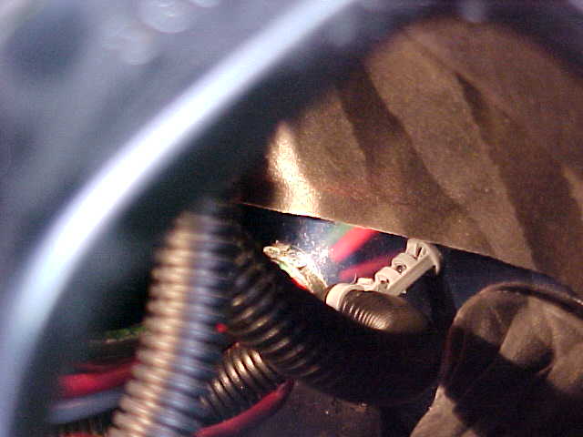
He knew just the right place to drill to avoid problems and he dressed down the sharp edges of the hole and used a large plastic grommet, large enough to clear all of my cables. He used cable ties where needed and did a nice job. I've tried to take some pictures of just where the hole was made and it's quite difficult to see exactly where it is due to all the brackets, hoses, and other cables which block the view. The following pictures might help someone trying to duplicate the feat, should you be braver than I and want to save some money. Although these pictures don't provide a perfect view of the hole, perhaps there are enough of the pictures for a person to recognize surrounding pieces and items and get a good idea for themselves.
You can get a better look at these pictures, a larger version, by clicking on the picture. Some of the pictures have been photographically enhanced so you can see better but still, it is very difficult to show a good picture down in the bowels of the vehicle. Too many braces, brackets, and pieces in the way of a good picture. Sorry.
This
picture shows the power cables entering the hole and grommet.
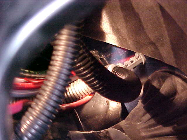
 A side
view standing on the driver's side and shooting through a fender bracket.
A side
view standing on the driver's side and shooting through a fender bracket.
 This
shows the cables as they disappear down toward the hole and grommet.
This
shows the cables as they disappear down toward the hole and grommet.
 Perhaps
you can recognize similar hoses and pieces to give a better idea where the cables are
entering.
Perhaps
you can recognize similar hoses and pieces to give a better idea where the cables are
entering.
 Again,
shooting through the fender bracket.
Again,
shooting through the fender bracket.
 Also
through the fender bracket
Also
through the fender bracket
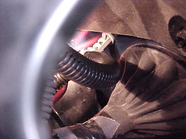
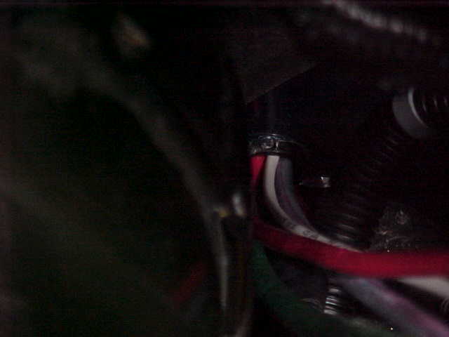
 Here the
cables are drawn together as they enter the firewall.
Here the
cables are drawn together as they enter the firewall.
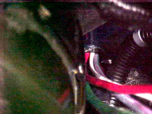
 This is
a higher-angled shot with the fender bracket more clearly defined.
This is
a higher-angled shot with the fender bracket more clearly defined.
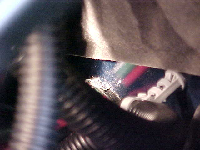
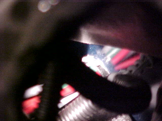
 This
would have been the best shot showing cables as they enter the firewall through the
grommet but it was difficult to light that area. The picture beside the original is
an attempt at photo enhancement. Perhaps it will help somewhat.
This
would have been the best shot showing cables as they enter the firewall through the
grommet but it was difficult to light that area. The picture beside the original is
an attempt at photo enhancement. Perhaps it will help somewhat.
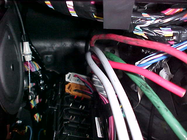
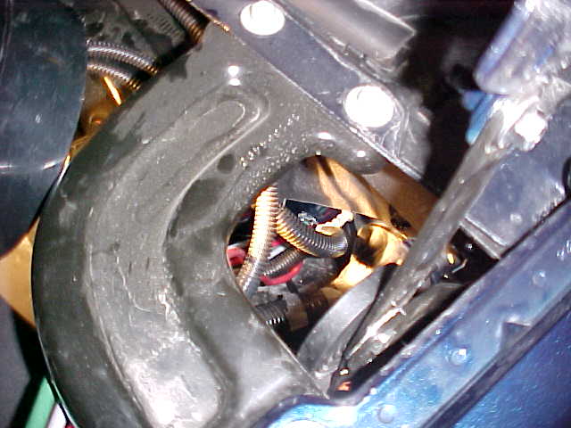
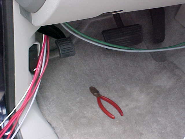 This view, from the inside is by standing beside the driver's seat. The cables come
through the firewall near where the driver's left foot would be (assuming that the driver
is seated correctly in the seat.)
This view, from the inside is by standing beside the driver's seat. The cables come
through the firewall near where the driver's left foot would be (assuming that the driver
is seated correctly in the seat.)
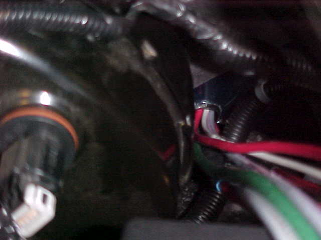
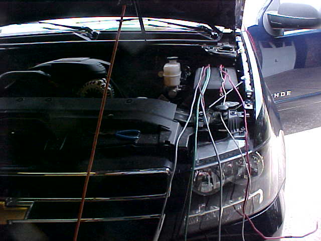
Under the hood you can see the power cables, obviously before they had been hooked to the fuses and the actual power.
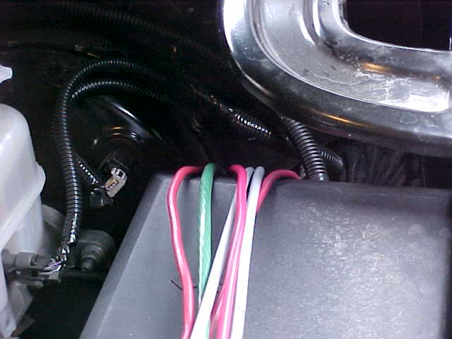
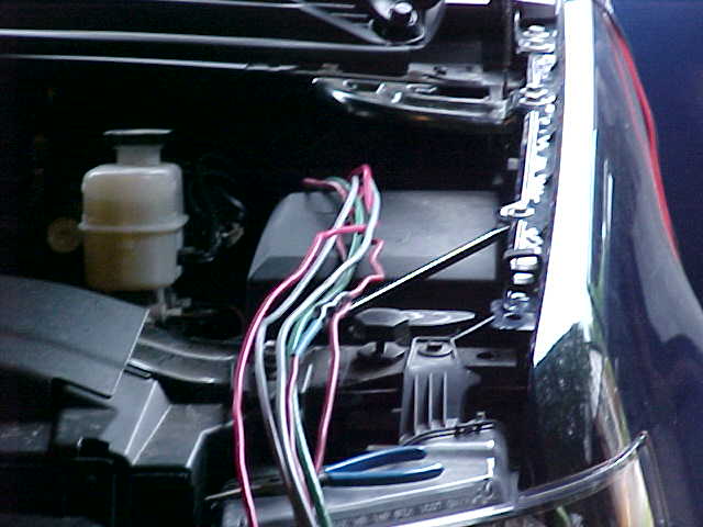 The
cables here are passing over the plastic box containing the vehicle's fuses and circuit
breakers. Here they travel downward and through the grommet and through the
firewall.
The
cables here are passing over the plastic box containing the vehicle's fuses and circuit
breakers. Here they travel downward and through the grommet and through the
firewall.
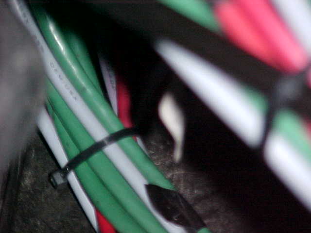 You
can see the wad of heavy cables bound together with a cable tie. The gray cables are
RG-8X cables for the antennas.
You
can see the wad of heavy cables bound together with a cable tie. The gray cables are
RG-8X cables for the antennas.
 This
project is far from completed.
This
project is far from completed.
 A
close-up look at some of the cables to be run through the firewall.
A
close-up look at some of the cables to be run through the firewall.
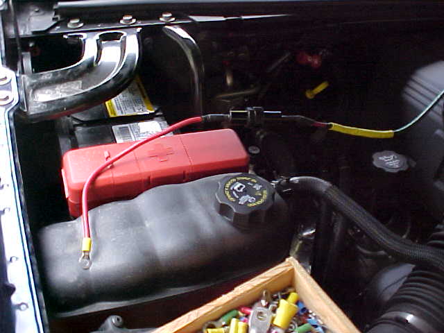 This is actually the negative lead.
Since the vehicle's battery is on the passenger side the heavy negative lead here was
attached to an incorrectly colored red lead ......... temporarily. The reason for
this was, the red lead already had a heavy fuse holder and fuse installed and it already
had had the proper ring terminal, type and size, on the end. I say this is a
temporary set-up lead but I wouldn't put any money and its "temporarity" ever
going away.
This is actually the negative lead.
Since the vehicle's battery is on the passenger side the heavy negative lead here was
attached to an incorrectly colored red lead ......... temporarily. The reason for
this was, the red lead already had a heavy fuse holder and fuse installed and it already
had had the proper ring terminal, type and size, on the end. I say this is a
temporary set-up lead but I wouldn't put any money and its "temporarity" ever
going away.
The Tahoe has two platforms for battery placement, one on the driver's side in the front corner and the other on the passenger's side, just in front of the firewall. Our Tahoe uses the latter so our battery is on the passenger's side. The battery platform measures approximately 8 1/2" x 10 1/2"
The fuse box for the vehicle is located behind the battery platform on the driver's side. In fact, the fuse box is actually between that battery platform and the driver of the vehicle and this vehicle has many fuses and circuit breakers. It can be accessed by removing the large black plastic cover protecting the fuses. The tray holding the fuses can be lifted to provide access on the wiring side by raising the two gray pieces on each end of the tray. These gray lever handles are stored in a down position but, when raised to the up and down position, allow the tray to be pulled up.
The gray handle on the front also covers two large metal studs. These are actually studs to allow power to the owner's own accessories. Standing in the front of the vehicle and looking at the fuse box, the left stud is fused at 30 amps and the right stud fused at 40 amps. This seems a bit odd since the larger stud on the left is fused for the smaller amount (30 amps). I'm sure there is some remote logic for doing it this way but that logic totally escapes me. (Come to think about it -- there's a LOT of logic that totally escapes me...... but that's another story.) The fuses used are the small 5/8" square fuses just behind the studs.
I've located several fuses which seem to be only powered when the ignition switch is on: #42 (FWD) 15A, #4 15A, #5 15A, #8 10A, #13 20A, #18 10A, #19 15A, and #23 20A. I have actually now made the attachment to #42 to provide +12 volts to a relay when the ignition switch is on. This keeps me from running down the battery if I forget to turn off the transceiver when I walk away from it. ........... forget........... me????? would I do that?????? yep....... that;s already happened once before I fixed this system..
To attach to the fuse, I removed the fuse, pealed the insulation back on a piece of #18 stranded wire, placed the bare stranded wire in the fuse socket and plugged the fuse back in. The prongs on the fuse press the wire strands solidly against the fuse holder and saves having to try to solder something where you might later not want something soldered. I did place an in-line fuse holder and fuse in this wire which goes to one side of an A relay with the other side of the relay coil going to ground. The A relay is the type used to control the high current going to a vehicle horn.
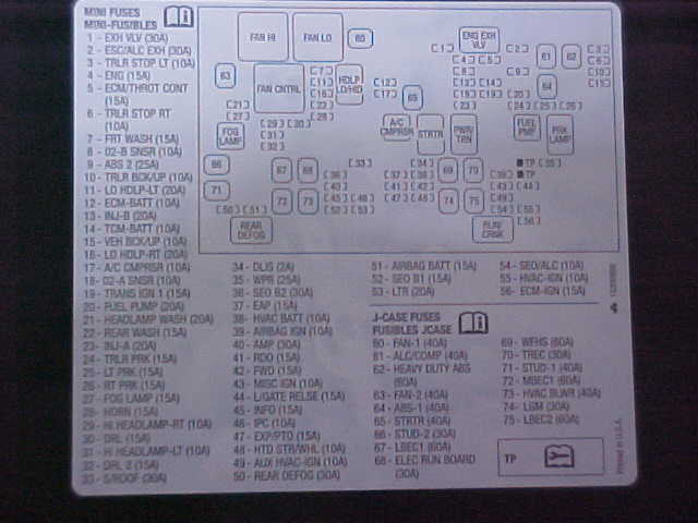
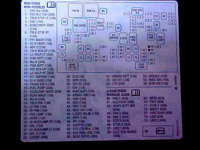 This was the best picture I could come up with for the fuse/circuit breaker layout for
this Tahoe. Again, the picture beside it was another attempt at photo
enhancement. I believe it makes it a bit easier to read.
This was the best picture I could come up with for the fuse/circuit breaker layout for
this Tahoe. Again, the picture beside it was another attempt at photo
enhancement. I believe it makes it a bit easier to read.
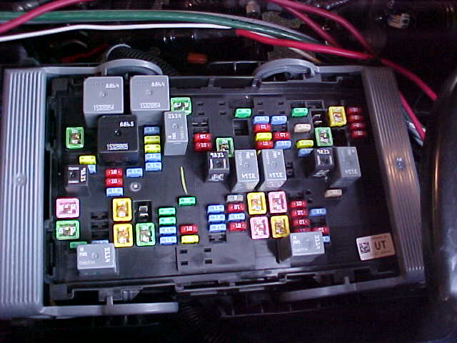 Here is the actual view of the fuses and circuit breakers which are shown in the diagram
above.
Here is the actual view of the fuses and circuit breakers which are shown in the diagram
above.
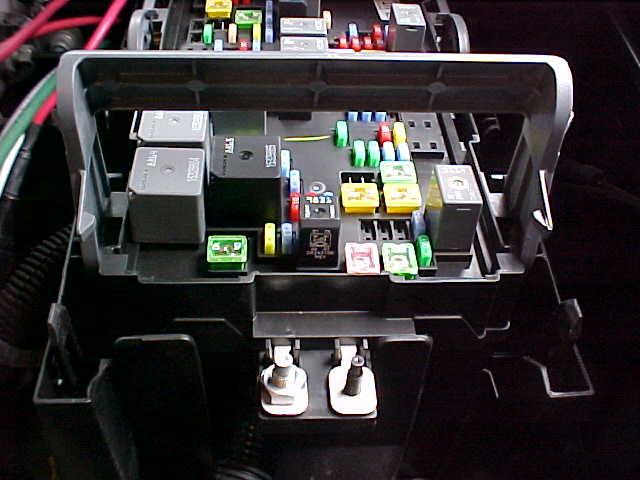 A closer look and you can see the studs provided for the user. I chose not to go
this route but to provide my own fuse setup.
A closer look and you can see the studs provided for the user. I chose not to go
this route but to provide my own fuse setup.
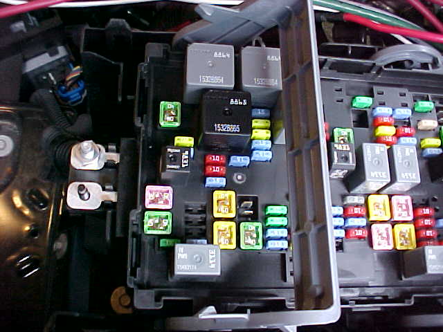 The pink and green fuses just to the right of the two studs are the fuses to the
studs. By looking carefully you can even see the pink one (which is to the
larger stud) is marked 30 and the green fuse (which is to the small stud) is marked
40. Go figure......
The pink and green fuses just to the right of the two studs are the fuses to the
studs. By looking carefully you can even see the pink one (which is to the
larger stud) is marked 30 and the green fuse (which is to the small stud) is marked
40. Go figure......
There will be additional information and pictures to show both ends of the cables. At this time, this is all that I've been able to document. If you see something which needs an answer, please drop me an e-mail.
Written August 7, 2007
Updated 09/30/07 05:10 PM
Page visited 949 times