Running the Power
The mobile installation I had prior to buying the truck was installed with too small power cabling and too little thought to proper procedures. As a result, I never had sufficient current available and the voltage drop was noticeable every time I keyed a mike. I was determined that this would not be the case on this installation.
The 12 volt + power cabling consists of two #10 parallel cables which run from the fuse block next to the battery, back through protective casing to the back where both the IC-706MKII and the DR-610 units were installed. This parallel run is switched by a heavy 12 volt relay which is keyed on by the ignition circuit. There is also another #10 cable for 12 volts + which runs to the back and it is not switched. It is fused next to the battery but runs directly back from the fuse block. This allows me to have a ready, always hot 12 volt + supply available all the time.
First, the cables are attached to the battery by using some threaded copper devices I picked up at a hamfest. They screw into the side terminals of the battery and allow the attachment of the three #10 cables as well as the regular vehicle connections to the battery.
The fuse block used was from a car audio shop and has a place for 4 large fuses. It is made for the folks who put high power amplifiers in their vehicles and drive around destroying their hearing and aggravating everyone within a block of their location. I used one for the relay controlled parallel cables, one for the single 12 volt cable and one for the ground lead which, according to safe mobile practices, is also fused. One fuse position is unused and allow for holding a spare fuse. The whole fuse block is covered with a plastic cover for protection. The picture shows how this is done. I mounted all of the power take-off pieces on a piece of pine board which sits directly atop the vehicle battery. Several metal clamps hold it to a brace and when it comes time to service the battery, the whole power board is easily removed.
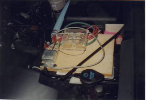
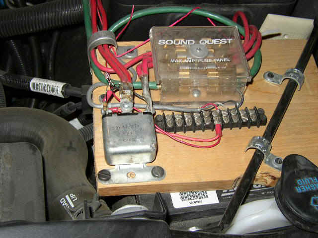
To orient the picture above, this is as though you were standing directly in front of the truck's engine compartment, on the driver's side of the vehicle. The picture show the pine board which covers the top of the battery, the fuse block with red (12 volt positive) cables going to it as well as the #8 green ground lead. The relay in the near left side controls the switched 12 volts and is controlled by the ignition switch. As an aside, the smaller relay control wire is also run through the blue flexible PVC tube to the rear compartment to allow switching the relay back there. I actually did this to quickly get things going before I had located the point which went hot when the ignition switch was turned on. In the back, I used the always hot 12 v. lead to close the relay.
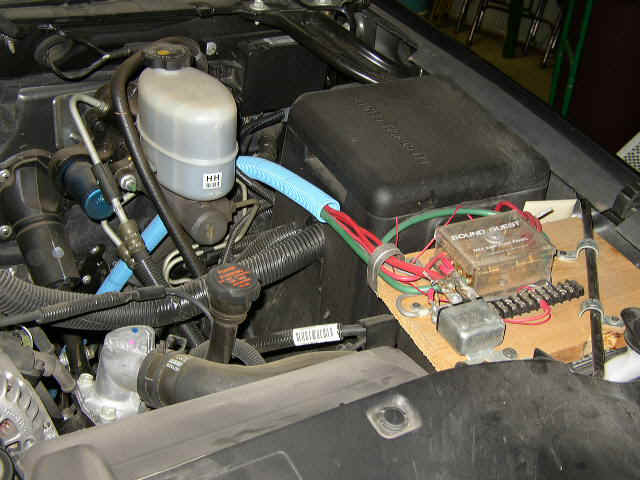
There is a terminal block in front of the fuse block where all of the cable connections are made. The blue PVC tube is a high temperature type tube and is relatively flexible. I inspected it almost daily for months to make sure it was rugged enough for my power run. It works well and the heat does not bother it at all, either from the engine compartment or the outside Oklahoma summers.
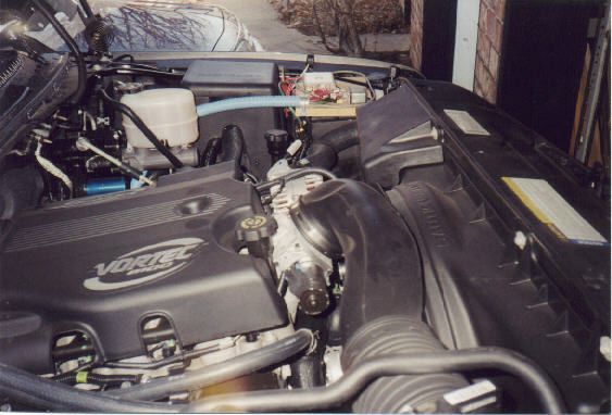
This shot is standing near the front of the truck on the passenger side and shooting across the engine. Perhaps this gives a better idea how the power connections are run. The blue flexible PVC tube does not run through the firewall but travels along on the underside of the truck to the back cab. The truck is a 4 wheel drive so this puts the whole frame even higher off the ground than most vehicles. There is little danger that the tube will be damaged. By the way, that engine is the 8.1 liter Vortec gasoline engine. That engine, along with the 4 wheel drive, would allow me to climb trees with the vehicle if I wanted to, I suspect. So far I have not had the desire to put it to that test.
Rather than running the cabling through the firewall, I chose to run under the bottom of the truck, come up into the cab through an existing hole in the floor. I say it was existing but it was somewhat difficult to locate. The company had thoroughly sealed it with some sort of tar-like plastic substance. The resulting hole, once the filling was removed, exposed a beautiful hole about 3/4" to an inch in diameter. As shown previously, the cables are protected from both weather and road damage by the blue pipe made of high-temperature PVC which has accordion-like pleats allowing it to flex. I also used PVC fittings to come through the floor and to protect the cables from any possibility of chaffing.
The next picture shows how the rigs are installed. There are actually two floor tiers to the rear installation, the first being on the existing ledge under the seat. This ledge is about 6 inches above the back floorboard. A very large terminal block is mounted on a piece of pine board and all of the power cables coming up through the floor terminate on that block. This allows easy connecting and disconnecting if any additions or modifications are done. The black device to the right of the heavy terminal block is a fuse block for additional devices. I don't know what else might be added but any device can be attached to that block with slip-on terminal leads and the blade-type fuses allow plenty of protection as well as expansion. The fuse block is currently attached to the 12 volt line which is hot all the time but could easily be moved to the relay switched power cable/s.
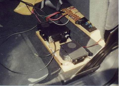
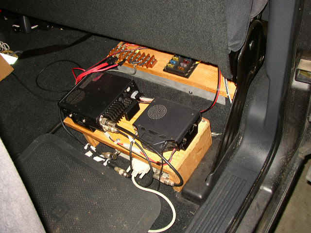
The radios (minus control heads) are mounted on a pine platform which sits on the floorboard below the ledge-mounted power block. In the picture above, the IC-706MKII is on the left, closer to the center of the vehicle, the DR-610 on the right. Both units have their own fans for cooling but I plan to eventually add one or two additional, outboard fans which will probably be thermostatically controlled. I have checked often and have not found the rigs to get too hot but I do much more receiving than I do transmitting. When I do add additional fans, the 12 volt power is easily available.
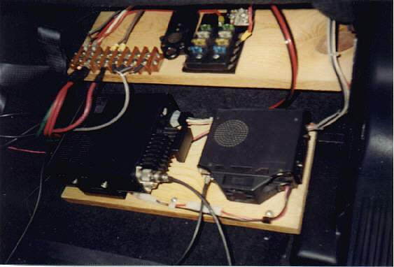
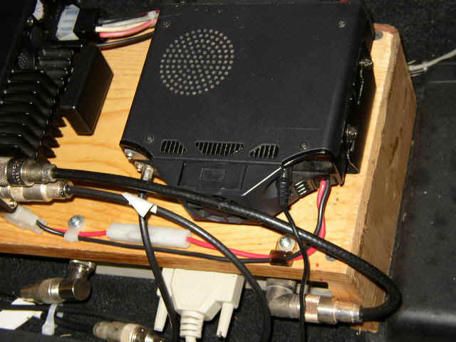
A larger view of the rigs show a bit more detail. The strange looking rectangular thing (top part on the picture above) on the power board looks like a microphone but is actually an old military switch. It can be easily switched on and off or has a locking device to keep it on. I bought it back in the 50s at the Army/Navy Surplus store because it looked so neat and was about all, as a poor kid without a job, that I could afford. Here, it was used to control the under-the-hood relay prior to my locating of the ignition point.
Although the rig wooden platform does not show well, it makes the rig board sit up several inches above the floorboard of the truck. In the space underneath, I place my LDG automatic antenna tuner. It also has a home-brew control head up front by the driver.
Not easily seen, but the coax cables for the antennas also come up through the floor through the PVC grommet. Underneath the floor, there is a PVC "T" connection which allow a double entrance of cables. The blue PVC tube carrying the power cables from the front enter on one side of the T and the coax cables from the back enter the other side.
The picture below shows the control head for the 706 mounted where it is easily seen by the driver. I struggled for quite a while trying to come up with just how I wanted it attached. When I had it near the floor to the right of the driver's right foot, it was difficult to see the display well and even more difficult to read the buttons.
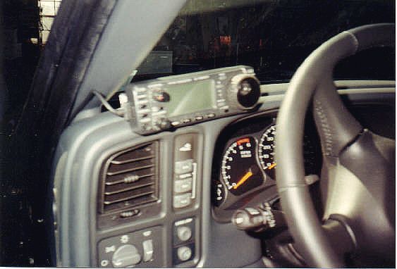
The system I finally chose was the one shown above. The control head is actually mounted on the little slide-in control head bracket sold by Icom for an inflated price but needed here. The bracket is attached to a piece of square aluminum tubing which is 1 inch square (available at your local hardware store where aluminum sheets, rods, and tubes are displayed). The 1" square tube is attached to the dashboard with double-faced tape. I can hear you wince at trying to use tape to hold it down, and I only planned it as a temporary measure until I could decide just where I wanted it. That crazy tape has been on for well over a year and shows no sign of trying to loosen. It has a small amount of play but, although it has seen some fairly hard use, it continues to hold. I'm not sure I could recommend it to everyone but it has sure worked well for me. If I were suggesting this method to someone else I would highly recommend that you buy a NEW roll of double-faced tape. I had some here that had been around for a long time and it wouldn't hold well for at all. The only reason I still have it is because I never throw anything away. Buy fresh tape and you may have as good a luck as I did.
Truthfully, this truck cost more than either the first or second house my wife and I had owned but since I tend to keep things forever, I was not opposed to drilling holes in it, either for rig mounting or antenna installation. I did not, however, have to do that. Any hole I needed was already there, thanks to Mr. Chevrolet.
The DR-610 VHF/UHF control head is mounted in the center overhead space above the mirror. This is the space reserved for the loose garage door remote control, several sticks of gum, and who knows what else. Information on this mount is available on another page. Click here for it. The 706 speaker and the control head for the automatic antenna tuner are on the floor in the center area between passengers.
I hope this gives you a few suggestions for mounting mobiles in the Silverado.
Page visited 523 times Click here to see my various ham radio call tags over the years
![]() Click here to return to Home Page
Click here to return to Home Page