Repairing a CDE/Hy-Gain/MFJ Rotator
Few things
are more frustrating to a ham than an antenna rotator which fails. It might be a failure to turn (either partially or
completely), a failure to indicate the (correct) direction, or an intermittent turning or
indicating. There are several companies, who
advertise in the ham publications, and are set up to repair or recondition rotators and
I’ve heard lots of good things about them. I
prefer, however, to attempt my own repairs on my rotators although there may come a time
when I’ll have to send mine off to the “hospital.”
If you, like me, want to tackle an errant CDE rotator, I’ve tried to describe the steps which I took to accomplish this. Hopefully, it will make enough sense that others can follow these steps and have the same success. I use the term CDE rotator since that was the original manufacturer back in the 70s when I had a ham store and sold them. CDE later sold their rotator operation to HyGain who made them for many years and then sold to MFJ Enterprises in Mississippi. Many, if not all, of the parts for the CDE rotors are still available from MFJ.
To begin all CDE
rotator repairs:
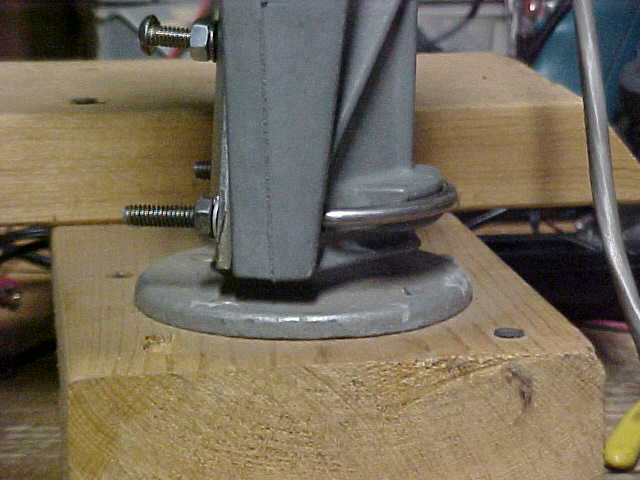 |
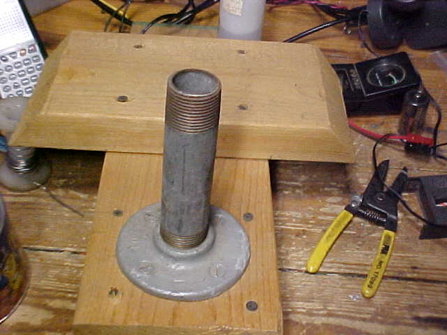
2. It helps to have a device with at least
a 1 1/2 inch pipe standing securely upright for mounting the rotor upside down upon. Mine uses a floor flange with a 4 inch 1 1/2 inch
pipe mounted on a small piece of 2 x 6
lumber. I'd like to tell you that my rotor repair mount was carefully designed and
built, just for this purpose. The truth is, I built it to use with my travel trailer
to act as a base for a mast holding a TV antenna. The beveled edges of the one 2 x 6
fit between the two wheels on one side of the trailer. |
 |
| 3. With a magic marker, make a matching
mark that lines up on both pieces of the rotor shell. |
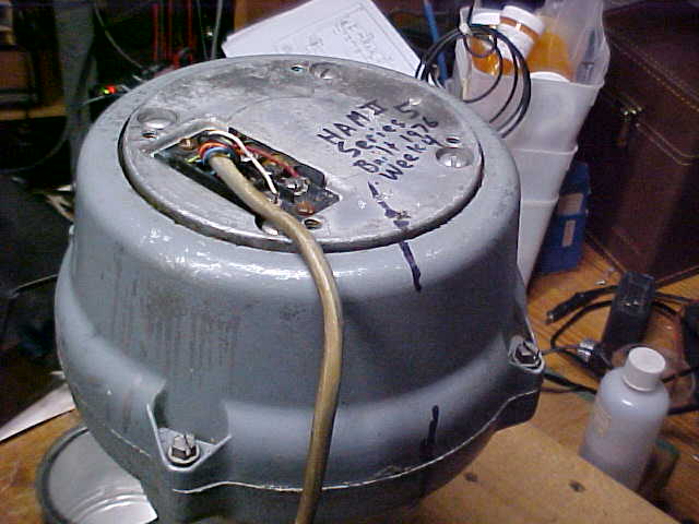 |
| 4. With a magic marker, make a matching
mark that lines up on the smaller shell piece (with the inside brake grooves) with the
bottom plate of the rotator. |
5. When the screws are removed, make sure
you can capture all the ball bearings, because they WILL fall out and try to cover your
table and floor. Be ye forewarned.
I received a note from George - WA2VNV with the additional suggestion:
I wish to add a suggestion about the ball bearing fallout problem. On my sailboat, I have to clean/wash & re-lube the winches which also have a bearing fallout problem. In this case, having a ball or bearing fall overboard is a more serious problem than chasing balls around the dusty basement floor! One of the simple tricks is to use an additional box top (approx 12 x 12 x 6 in (L,W,H)) with a round hole cut in the bottom sized so that it just fits over the pipe & flange that holds the rotor in place during disassembly. It will contain any/all parts and balls that fall out and also keep them clean. Then you can carefully transfer them to the other box top for inspection, cleaning, etc.
Good idea George, thanks.
NOTE: The bearing holders are plastic pieces which hold the individual ball bearings. These plastic pieces DO NOT fit either way. When disassembling your rotor, take careful note of the way they are mounted. If you think you might not remember the proper way they sit inside the rotator, take a digital picture of the bearings and races while they are still inside the rotator. This action, alone, can save you much time and frustration. Whether you finish this activity with all of your hair may depend on you carefully following this noted paragraph.
6. Have a container (top of large box)
handy to place the ball bearing races and bearings in a flat condition. There are typically two sets of ball bearings
(three for the Tail-Twister rotor).
7. When the bottom outer shell is removed,
take careful note of the way the bearing races are positioned and placed (as noted in the
NOTE: in red above).
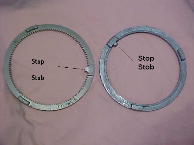
Ring Gears |
8. When lifting out the motor assembly, if
the ring gear is still in one piece, take note of where the end-stop stob is in relation
to the potentiometer and the rest of the inner assembly.
NOTE: Often with cast aluminum ring
gears, which were standard with the Ham M – Ham IV series, the cause of a rotor
failure is a broken ring gear. It is usually
broken into several pieces. The cast aluminum
ring gear can be directly replaced with the stainless steel gear that was standard in the
Tail-Twister rotor. Both of these gears are
available from MFJ and they often have them on hand at their hamfest booths. |
Stop stobs trip the "end of rotation" limit switches inside the rotator.
|
9. The bearing races and ball bearings can
be thoroughly washed out with gasoline but this must be done CAREFULLY and in an open,
outside area.
NOTE: I was severely chastised for using gasoline for this step and I agree that it's a poor thing to do. I do NOT recommend the use of gasoline as a cleaner since there are other products as good or better and less volatile. I was just saying, in this article, that I did use gasoline because I was in a hurry, I didn't have the proper cleaning product available, and I'm not very smart.
10. Big chunks of hardened grease should
be removed from the inside of the rotator as well as all pieces of the broken ring gear if
it was broken.
11. Clean all of the inner gears with a
cloth soaked in gasoline. Clean all of the
inner parts of the rotor.
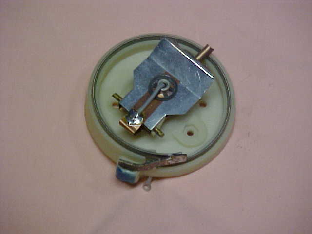
Indicator potentiometer |
12. If the indicator potentiometer is
intermittent, it may be dirty so that should be cleaned.
If the rotor was subjected to abuse or if it failed due to a nearby lightning
strike, part of the potentiometer may be burned away leaving an open circuit. I never did have much luck repairing a break in
the resistance wire on the pot since this type of wire is not generally solderable.
Since it lives in a pretty inaccessible area on the top of the tower, I prefer to replace
the whole pot unit. They are also available
from MFJ via a telephone call to their toll-free number or a visit to their hamfest booth. They are not cheap by any means but I believe
it’s worth removing a problem that might soon appear worse when I can’t easily
provide a fix. Also if you think the cost is excessive, just bite the bullet and buy it anyway. They're the only ones around who manufacture this piece and you won't find one "pretty much like the old one" anywhere else. There is no competition for this priority piece and it's not something you can duplicate in your home workshop. A good and clean indicating potentiometer inside your rotator and atop your tower or mast will help to assure that you can continue using your rotator to turn that beam and seek out that choice DX station as the propagation improves......... uhhhh, make that WHEN the propagation improves.
|
13. While the rotator unit is opened up,
and cleaned up, this is probably a good time to look over the wires and soldered
connections on the motor and the end-stop switches. Again,
any problem you find is much easier fixed now than during the next contest or blizzard.
14. Look
over the ball bearings carefully. If you see
any rust on a ball bearing it’s time to replace it/them and if one needs replacement,
I’d replace all of them. At one time I
looked in the yellow pages to find a bearing seller and replacement bearings for my whole
Tail-Twister were quite inexpensive.
15. When it is time to re-grease the
rotor, I used a grease which was recommended to me quite a few years ago. I’ve seen many different recommendations for
rotor grease and one may be just as good as the next.
When I wanted to find a good grease, the folks I talked to who were “in the
know” recommended a grease with both cold and hot temperature operation and what I
bought was “High Temperature Grease LC #2” from Lubriko Lubricants. The container advertises “Operating
Temperature Range –40�F to 400�F (Intermittently to 450�F)” so I felt like
that pretty well covered my typical station operation.
This grease is the typical greenish-brown color.
It comes in a tube about 9” tall and 2” diameter. I’ve used it several times and still have
plenty, although the mass to dip into is getting just past the length I can reach with a
finger. I may have to go borrow one of my
wife’s butter knifes for the next grease job on a rotor rebuild.
16. Once greased up good, and with all of
the necessary parts repaired or replaced, it’s time to re-assemble the unit. Again, the top rotor shell should be clamped to
the bench pipe and placed with the inside center potentiometer moving molded piece
forward.
17. The ring gear should be placed with
the end-stop stob to the assembler’s left or to match the direction it was when the
rotator was first opened in Step 8.
|
|
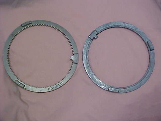
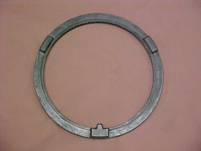
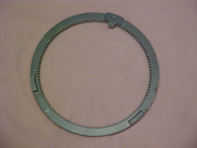
On the left is a cast aluminum ring gear. On the right is the stainless steel ring gear. The two are interchangeable but the stainless steel gear is about triple the price of the other. |
|
18. Note also that the bearing races are
placed in the groove in the same direction that they were in Step 7. For my rotator, it placed the smooth side of the
plastic race up toward the inside of the rotator.
19. Load one bearing race onto the
machined groove around and near the top of the rotator shell. The race should have all of the bearings, whether
new or old, installed and gooey with grease. Usually if you continue to hold the race in
its natural circle, the bearings will stay in. If
the re-assembler gets too careless and lets the ends of the race come apart very much,
some (or all) of the bearings will come out and let gravity determine their fate. Remember that they are now gooey with grease and
they will land where they can do the most damage or where they can pick up the maximum
amount of dirt and dust bunnies on the floor. Extra
care during this operation will be worthwhile and make you much happier during the coming
hour(s).
NOTE: One reader, who obviously has tread this path, wrote me with the following comment: "There are two kinds of people in the world. Those who have chased those ball bearings all over the shop floor, and those who have never opened a Ham-M, Ham IV, T2X, etc." I can only say, "Amen"
20. Place the potentiometer to the center
of its range. Carefully lower the motor
assembly so that the potentiometer copper spring engages the molded piece located on the
inside top of the larger rotor shell. It is
very important that this piece be placed properly since, if it does not, the meter will
probably indicate movement in one direction but not the other and will stay where it ended
up on the first turn. Like the old
carpenter’s axiom, “Measure Twice, Cut Once” it is important to spend some
time to do this operation very carefully.
21. If everything is seated correctly, the
inner gears will be engaged in the ring gear, the potentiometer will be properly engaged
in the piece in the top of the shell, and the motor assembly will be centered within the
shell. You're looking at the rotator's 8-pin
terminal strip which is now on top. You should be able to see equal spacing around
the motor assembly piece as it is now resting on the inner ball bearings. If you are able to easily attach the rotor
(seated upside down on the pipe) and the control box via a piece of 8-wire cable, it would
be a good idea to try out the box. If all is
OK, the rotor will turn a full 360 degrees and should automatically stop at the extreme
ends of its travel. If this does not happen,
the problem MUST be corrected at this time. Do
not go ahead and reassemble the two shells, HOPING that it will somehow fix itself and all
will be OK…………. it won’t!
Guaranteed, it won’t!
22. If, however, you see it turn a
full 360 degrees and see it stop at each end of travel, sit down for a minute and
congratulate yourself on your deed. You’ve
accomplished the most difficult part.
23. Ah, but now, back to work. The final bearing race, full of gooey greasy
bearings, is ready to be placed in the groove atop the piece on which the motor is
attached. The same caution as noted in Step
19 should be noted here too. The only
difference here is, since you’re almost finished with the job, any ball bearings
dropped now will roll down the heating vent or will disappear
completely………… never to be found again.
Please don’t ask me how I know this, just take my word for it. The bearing race should be placed in the groove in
the same direction that they were in Step 7. For
my rotator, it placed the smooth side of the plastic race down toward the inside of the
rotator. The ball bearing races in my rotator
go with the flat part of the plastic toward the center, i.e., when fully assembled, the
two bearing races flat pieces face each other to the inside.
NOTE: At one point I was having difficulty in reassembling my rotator. It was just a small amount too thick and when the final screws were tightened, the motor stalled and refused to turn. The problem was a failure to get the ball bearing races in properly. That's why I reinterate that you should check which way these races originally were installed as you take the unit apart.
24. Now it’s time to place the bottom
piece back on the top shell. If you marked
the two pieces correctly back in Step 3 they should match up perfectly.
25. Find where you put the screws removed
from the case and tighten them down securely. Remember
that this rotor will be where you can’t get to it very easily so give that wrench
just one more little tightening on each screw.
26. You, sir or madam, are now finished. Your rotor should be ready to reinstall on your
mast or tower or whatever and be good for another 20,000 miles……….. or
perhaps 20,000 contacts.
=============================================================
Created January 6, 2007 The page was updated on 04/11/08 09:54 PM
Click to
return to Rotor Repair Menu ![]() Click to return to Home Page
Click to return to Home Page ![]()