Note: This unit was in my Sierra 30 foot trailer
When spring came and I prepared to get my RV all un-winterized and ready to take out, I discovered that my trailer battery was nearly dead. Since it was new from just the year before, I thought I wasn’t getting very good mileage on batteries but I thought I would do some other checking before indicting the battery as defective. First, doing some various voltage checks, I found that I had good 12 volts DC to my interior lights and to the voltage monitor on the control panel. Hmmmmm….. that’s odd. That voltage was coming from the power converter 12 volt supply (although not from the converter's battery charging section).
Checking the cigarette lighter socket, it only showed 5 volts and I determined that this was coming directly from the battery which was, by then, in a near discharged condition. Although the trailer had been plugged in all winter, the battery had not received any charge since the battery charge feature in the power converter had failed in my Magnatek Power Converter, and I didn’t know when that had happened. The battery was OK, the Magnatek higher current 12 volt section was OK but the battery charger section of the converter was not OK.
Checking at the Magnatek panel in the bathroom, I found no voltage between point C (which was the positive side from the battery) and point D (which was the negative side from the battery). Now I knew where I had to concentrate my attention. NOTE: Points C and D are actually labeled as such on the unit.
At this point I spent several hours combing the Internet in search of a schematic for the Magnatek converter….. totally without success. I read jillions of messages from RVers, several asking for the same thing I sought. I wanted any kind of information, particularly a schematic, for this unit. I even contacted some of these people to ask if they had been successful in the search. Nope…..nada…..nothing....... no such luck.
I found a telephone number for the factory which built the unit and even tried to call for info. Human help was available for warranty work but my unit was several years out of warranty. I was out of luck.
I needed that schematic and since it was unavailable, it looked like I would have to generate one myself. If you’ve ever tried to do this it is akin to somewhere between trying to write down a cake recipe from only having the completed cake in front of you and unscrambling an egg. Not much fun, especially if the parts have non-standard markings or no markings at all........ like my converter.
I was ultimately successful and the schematic I have included is close enough, if not an exact rendering, of what is found in the Magnatek power converter. I hope it helps others as it helped me. Now, with schematic in hand, I returned to the project of repairing my converter.
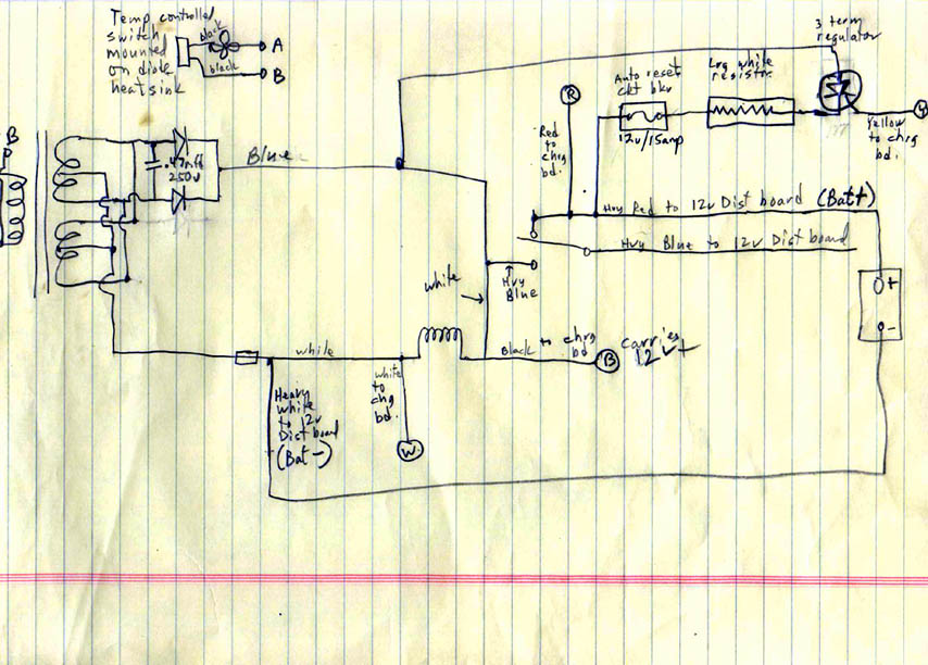
PIC #1: The circuit schematic is actually in two parts. The first part, shown above, is the main power supply part of the converter. Thanks to a reader named Baldy in California, you'll be able to see the pictures better than they originally were displayed. Baldy took my original pictures, which were upside down and sideways, and corrected them for me. Thanks Baldy..
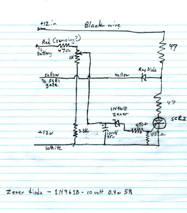
PIC #2: The schematic above is the battery charger part of the power converter. It will charge the RV battery but then automatically taper down to a trickle charge so as not to destroy your expensive battery.
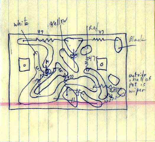
PIC #3: I included this picture but I'm not absolutely sure of its total accuracy. I drew this out several times and I think this was the final version. Don't hold me to it, however, and if there is a discrepancy between the schematic and the underside of the PC board, you should believe the schematic first.
UPDATE NOTE: Since publishing this original article someone sent me the actual schematics on a Magnatek RV power supply. Click here to go to copies of those two new pages.
CAUTION: When you decide to work on your power converter, be sure you unplug your trailer’s power cable from the 117 volt AC mains. Once that is done you can remove the screws holding the panel/cover onto the converter. This will expose the transformer, diodes, solenoid, fan and battery charge board. This solenoid is energized whenever the trailer is plugged into external AC power and it allows the converter to send charging voltage to the trailer battery. Magnatek chose to use a solenoid to activate a switch to perform this function rather than use a relay. Why? I don’t know.
The following are steps required to remove all connections so you can pull the whole power converter out to work on it:
1. Remove the 4 hex-head screws which hold the front board.
2. Remove the 2 hex-head screws holding the other board.
3. Remove the 12 volt wiring to the 12 v. distribution board – the white and red wires have screws, the blue (12v) wire is attached with a screw and nut.
4. Open the cover to the 117v AC circuit breakers.
(You did disconnect the 117v AC didn't you?)
5. Remove the white wire which goes to the left side vertical screw strip.
6. Remove the black wire coming from the far right-hand circuit breaker.
7. Carefully feed the 2 AC and 3 DC wires from the top box so they are inside the bottom power supply box. Now you can remove the power converter pieces.
8. With the power converter box on the workbench, remove 2 hex-head screws holding the nylon posts which are holding the battery charger circuit board.
9. NOTE: With the power converter box on the workbench, the top cover can be removed with 4 hex-head screws. This allows full access to the inside components.
The next step is to remove the board containing several electronic parts including resistors, silicon controlled rectifier, zener diode and a capacitor. This board, on my unit, stood vertically and was attached to the right-hand wall of the supply. NOTE: Do NOT attempt to pop the board off the nylon posts where it is mounted. It will not come off and attempting to pop it loose will result in a cracked board, which is made of rather fragile phenolic material. Breaking that board can separate traces on the printed circuit board and you will have additional problems. The board can be removed but only after the whole box, holding the supply, is removed. (A word to the wise….. I hope.............. ask me how I know this...... No......... never mind.)
It is now that you must use your electronic trouble-shooting skills to determine which component or components might be causing your problems. That is rather difficult for me to tell you what might be causing your converter to fail but, hopefully, this information and the schematic provided will allow you to find it.
My problem turned out to be the large rectangular resistor mounted with a pop rivet to the back panel of the box. The value was obscured on mine but an ohmmeter check showed the value to be more than a megohm which was much, much too high. I would guess that its true value should have been less than an ohm but at a high power rating, perhaps 50 – 100 watts. It was here that I had to do some guessing. Since this resistor is located in the line providing charging current to the trailer battery, my guess is that its function is to drop the load a bit when first connected to a battery which is totally discharged. A fully discharged battery would place a tremendous temporary current load on the power supply components and this resistor helps to protect things during that initial surge.
After the repair was complete, I did some checking on the converter to see just how much current was provided to a battery for charging and to see whether the higher current stayed up at the high level or if it tapered off to a trickle charge as this type of circuit should do. With a 0-3 amp meter in series with the battery charging line, and using no extra resistance in the line (the big white rectangular resistor was shorted to make zero ohms or there-abouts), I placed the charging circuit across a pair of 6 volt/7.7 AHr lead-acid batteries which I had on hand. The ammeter started at just above 2 amps charging, then tapered down to around 1.25 amps.
Then I tried it across a 12v/7 AHr lead-acid battery with was already charged. The current started a just below an amp and within a minute, dropped to about 200 milliampres or .2 amps. I say "about" because the ammeter constantly wiggled the equivalence of .1 amp. I suspected that this might be caused by the noticeable AC ripple in the DC line. After all, there is no filtering on the rectified DC coming off the full-wave rectifier.
I located a 2 ohm, 50 watt resistor in my junk-box to replace the defective one which had originally caused my problem. Placing the charger wires across another charged 12v/7 AHr battery it started the charge current at less than an amp. It also tapered down, within a couple of minutes, to about .2.amps…… a shaky .2 amps. The resistor did not even run warm but it had very little current through it.
I finally found a .25 ohm/5 watt resistor and placed it in the place of the original defective white rectangular unit pop riveted to the back wall of the converter. I feared that the power rating on this resistor might be too low but I have used this one for several months and it is holding up well.
I reassembled my converter by going in reverse with the steps taken earlier to disassemble the unit. Everything went back together as easily as it had come apart and I was a happy camper (so to speak). I hope, if you are having problems as I was, that you can use some of this information and have as much success as I did.
One additional piece of information – the fan which you hear while the trailer is plugged into an external 117 v AC source, is actually running on 117 v AC rather than 12v DC and is thermostatically controlled. A temperature sensor is attached to the aluminum heat sink which holds the power diodes. When they are doing their job and supplying 12 volt power to your trailer (not particularly to the battery) those diodes will run hot and make the heat sink also quite hot. The sensor turns on the fan which blows across the heat sink as well as our now familiar power resistor. If you don’t hear the fan then the power converter is not having to do much work and the fan gets to rest.
One other benefit on my converter is, I was able to clean up all the dust and "grunge" around the fan and it has become much quieter. I still hear it but nothing like it was previously.
Just as a final encouragement for you to try to repair your own converter, when I looked up the replacement converter in a trailer accessories catalog, the replacement unit was between $200 and $300. That was enough inducement for me to attempt my own repairs.
Jim Pickett – K5LAD
Written June 29, 2002 ---- Updated 07/07/10
Updated Additional Information
I received an email from Pete Sweeny with the following information and I thought it was very worthwhile to add here:
Good evening, I found your article most helpful. I recognized the resistor as what is commonly called an ignition resistor or ballast resistor. They were used in many Chrysler products before electronic ignition systems came into use. I found that a Sorenson brand part number GCR7 will work, it is available at Advanced Auto parts for $3.88. It has no potting material around the resistance wire thus it will run cooler as well as a raised place where the unit fastens to the cabinet, this will also allow for better air flow. Thanks PeteAfter learning it was the same resistor as in the old Dodges, the same ones that we ALWAYS had a spare of in the glove compartment, I checked that first. I jumpered it with my ammeter when I had the battery out and all the lights in my camper would work. They have not done that since I bought it used! No wonder my battery would not charge while plugged in! I then removed it and ohmed it... open circuit. The new one cost me $8.99 at the Canadian Tire store part # 18-4506 ( for us Canadians )
I just wanted to thank you for saving me the cost of a converter!
Thanks Tom
I replaced my fan with a 117v AC muffin fan which was about 4" square, as I recall. These fans should be available in electronics supply stores, hamfests, or even computer stores. The one I used was from the surplus market somewhere and was one I had kicking around. If you go this route, be sure you get a 117v AC unit as a lot of the fans you'll find surplus are 12 volt DC. The Magnatek fan only runs when you're plugged into city electrical mains.
As far as other parts for the unit --- "official Magnatek parts" I once had a catalog I got from an RV store. I tried to find it today but, alas, no luck. I dug back through some older messages and will copy what I sent to another RVer about this book:
Sounds like you found a pretty good deal and I think that might be wise. I might recommend that you find a book (actually a catalog) called "2004 RV Parts & Accessories." It's an 8 1/2 x 11 inch book that's just over 3/4" thick. I got mine from one of the RV dealers in Tulsa and it was a freebie. I don't know if you've got some of those around you but it might be worth a call to a dealer or two. It's one of those books which is published for "the world" but has this dealer's name, logo, address, and phone numbers on the cover. They say that many of the items in the catalog are stocked but if you find something which they don't have, they can order it for you......... kinda like the old Sears and Roebuck catalogs. In this catalog I found, not only brand new items (including power converters) but also some (note SOME) parts to repair existing equipment. For instance, on page 116 I'm seeing replacement parts for Magnetek Converters like: door latches, limit resistors, the PC board, fan motor, and relay. The prices are surprisingly economical.
Perhaps if you can locate a store with one of these books you could find a direct replacement for your fan. The truth is, the muffin fan I put into my unit is a LOT quieter than the old original fan.
Thank you in advance,
Mark
My answer to him might be helpful to others who have had the same problems and question: Hi Mark -- I'm certainly no expert on Magnatek converters........ I'm just someone who was desperate because mine was broken and I couldn't find any information on the Internet about it. Necessity is the mother of invention, at least it was for me.. .......If I were testing my converter to see if the temperature switch was working, I'd set it up on the bench and blow a heat gun (or my wife's hair dryer) on it. If the converter was plugged in to 110 volts AC and the fan didn't come on (with that heat on it), I'd know that either the fan was defective or the temperature sensor was bad. Actually when I store my trailer at home, I keep it hooked to the AC mains all the time. When I go inside on these really hot days, my fan is usually running. Not because the converter is generating lots of 12 volt DC power, but because the excessive temperature closes the temperature sensor switch in my trailer. If the fan doesn't come on when you blow hot air on it, disconnect it from the AC mains and try the heat source again. Once it has been heated up, measure across the temp sensor switch with a continuity meter - or a VOM (Volt Ohm meter) set to low ohms. You should see either a short across the switch meaning that it has closed or at least a low resistance (only a few ohms at most). If that test fails, the sensor is bad and must be replaced (try an automotive supply store). If the switch closes with heat, then it's good and the problem is probably a fan which needs to be replaced. The fan is a 110v AC fan and not a 12v DC fan like they sell at computer stores. Don't put a 12v DC fan in there --- it would run REALLY FAST but not for very long before you would let all the smoke out of it. Be sure any testing you do with that meter and any replacement of any of the parts is done AFTER TURNING OFF THE POWER - the 110 v AC!!!!!!! BTW - If you must replace the temperature sensor, they'll want to know what temperature it should close (be sure you get NO or normally open). You might look on the switch itself and see if you can find a stamped number for the temperature for it. If not, like I said, my switch is closing in a closed trailer on a hot day which is probably around 110-120 degrees so I'd start somewhere around there. I hope this has been some help for you and your friend. Good luck and 73, Jim - K5LAD BTW - Yes, he needs that fan or it WILL overheat...... badly overheat. He will need to get this fixed. ---------------------------------------------- Then I quickly added another message: BTW Mark -- I saw something just as I sent you the previous answer. If you must replace the thermal sensor switch, don't use the term you used in your message here. The switch in the converter is NOT a "thermal breaker" but is a thermal sensor switch. The difference is, a thermal breaker is NC or normally closed and when it reaches a defined temperature, it OPENS and breaks the circuit. The switch in the Magnetek converter is a NO or normally open switch and it closes when the designed temperature is reached -- when the converter is running and gets plenty hot and the fan is to start up to cool things back down.Again, I hope this helps.
Jim - K5LAD
Here is yet another email from someone who ran across my web page and used the information available to repair his Magnetek converter. He went one step further and is sharing the additional information he found which should help others.
On 23 May 2008 at 18:34, Ken Avery wrote:
Hi Jim;I recently had an issue with my Magnetek and found your article on the web. First, Thank you, article was very helpful. I also had a problem with charging and you article cut me to the chase right away. My resistor, however, still had numbers, after a couple web searches and e-mails, I arrived at the answer, numbers were, HEI PC50-.15 P10. Translation is as follows,
Huntington Electronic Inc., 50 watt, .15 ohms, +/- 10%. From manufacture, $10.00 each, minimum 5 piece order, plus shipping.
Resolution; Newark Electronics, SKU: 28K6344, 50 watt, .15 ohm, +/-1%. $4.83+shipping. Charging the battery like a charm.
Unit is on a Layton 24 foot fifth wheel, 35 amp Power Converter, Series 6300A, Model 6332 option QB.
Thanks once again Jim for posting you article on the web, hope this info can help someone else as well. Cheers and happy camping.
Ken Avery
Thanks Ken - Jim
Thank you for info and for circuit diagram even more. My resistor R1 had value on it. It is 0.3 Ohm 50 Watt. CB1 was my problem (Circuit breaker) and value is 12 Volt 10 Amps.
Bought in Napa Autoparts store. My unit was in Okanagan Camper and now is working okay. Original problem was battery not being charged. Everything else worked just fine.
Al
OK Al, Good to hear another success story. - Jim
Here's another from Chuck from
February, 2009. He was able to find some additional part numbers and repair his
converter:
Hi Jim,
Thought I'd send you an update and let you know how my repair went. I did basis troubleshooting with the unit still in the 5th wheel. As suspected, I had the ~12-13 volts on one side of the power resistor and nothing on the other side. Suspected it open. Jumpered it briefly with a wire and confirmed that everything not working was now working. At my age, LOL, laying on the floor too long hurts.
I removed the bottom unit per your instructions. A piece of cake, thank you. I removed the top metal plate and unsoldered one end of the resistor. Confirmed--open resistor. I couldn't find the part you recommended, but searched the auto part stores for a comparable ignition resistor that was readily available. I found a 1.6 ohm 10 watt ignition resistor made by NIEHOFF part # FF109. Used commonly in many Chrysler cars. Concerned about the ohmage, I found a .3 ohm 10 watt power resistor at a local electrnonics distributer. I soldered the 2 together in parallel and with my poor meter read about .4-.5 ohms. I figured the combined wattage to be about 20 watts. Installed them in the unit and all looked good. Checked the fan circuit and the thermister and all looked good. Re-installed in the 5th wheel and has been running for 3 days now with no problems. Current seems right and the resistors are barely warm and the batteries are now charged fully.
Once again, Thank you so much for your and everyones help. Saved me about $250 . My cost for both resistors was about $8. Thank you again.
Chuck
That's super, Chuck. Magnetek loses another handful of money due to users doing their own repairs. Thanks for writing. -- Jim
This is from John from January,
2009 on the same topic as above. He was able to find some additional part numbers
and repair his converter:
Jim
Your article was very helpful. I was working on the Magnetek series 6300A m/n 6345 which
is in my 95 Four Winds 5000 rv and found the same problem you described. Your
directions sent me to the same resistor that failed on your unit. After a little research
I found a direct replacement resistor from Master Techs, Inc. Their part number is
16506718 @ a cost of 10.00. The phone number is 800-848-0558. Thanks very much for taking
the time to post your experience.
John
Hi John --
Thanks for writing and I'm glad the article helped you. I get messages weekly from folks
who try to find repair info for these converters (on the 'net) and there just doesn't seem
to be much out there.
I prepared the original article several years ago when I couldn't find anything. I figured
if I had the problem then others might also. I makes me happy that it's been useful for
others. Hope you and yours have a very Happy New Year and get to spend many happy
hours in your RV.
73, Jim - K5LAD
Wonderful news update: (June 5, 2009)
Thanks to a reader named Chad Helmer, he's informed me that the manufacturer now provides the information on the Magnetek converters which we've long needed. Perhaps they realized, from all the hits on this website, that there was a major need to help and serve their customers. For whatever reason, we're all the beneficiaries. The manufacturer, Parallax, has provided this information at:
http://www.parallaxpower.com/linear.htm
In addition, Chad discovered a website which advertises the actual resistor which is often the problem and needs replacement when the converter refuses to charge the battery. It's at:
The price, at this time, is $7.61.
Thanks a MILLION, Chad. You've helped a lot of people.
Good information arrived from reader Garret Hansen in Canada. He found his resistor was also defective and his Magnetek power converter was not working. He wrote:
Thanks for the writeup. That was some very helpful information. I live in
Canada and searched the part number on the Canadian Tire site left in the one post on your
site but
was unable to find it. I will let you know if I am able to source a replacement part
locally in Alberta and you can post it to help others from Alberta find the part.
Thanks, Garret
Then he sent a follow-up message:
Hi,
I actually was able to find a supplier in Red Deer. Gord at http://www.kohen.ca/ that ordered
a  50 watt 0.15 Ohm resistor
today for me and should be in in two days.
50 watt 0.15 Ohm resistor
today for me and should be in in two days.
The link to Parallax was good in that it has some good pictures in it but when I emailed them about purchasing just the resistor it sounded like they wanted to sell me a replacement upgrade kit as you can see from the response I received below.
MagneTek that will likely not be available from anyone locally. You can try J & J Sales in Langly, B.C. at (604) 534-6336. If unavailable from J&J, I think your best option would be to install a 7345RU upgrade kit. Information is attached. J&J would also carry the upgrade kit.
Marty Redd
RV Technical Support and Training
Parallax Power Supply
- A Division of Connecticut-Electric, Inc.It looks like the company is willing to sell a parts kit which includes several items. If that would fill the need for readers on this webpage, the order number is listed above and the ParallaxPower link is listed above. Garret only needed and wanted the resistor to complete his repair so he continued to search available sources.
......the part number is MC14730 made by Multicomp.. http://www.newark.com/multicomp/mc14730/power-resistor/dp/28K6344 cost me $5.66 CDN.
Thanks Garret
I received another helpful piece of information from another RVer, Karl Reichert. He wrote:
Finally, after much searching, I have located a supplier of the fan temperature sensor (thermostat) for the model 6345 unit - I believe the company is in
Oregon, 1- 800-234-4328 part # 09526353 - unit set temp. is 140 deg. Cost less than $10.00. Company also carries many other RV parts, i.e. I also
purchased parts for A & E awning. Regards Karl
Thanks Karl. That is a very valuable note.
Thanks to Paul Burns, another RVer in Great Britain, he has collected a lot of excellent information on the Magnetek Power Converters which includes much of the information we had placed on these web pages. Paul has offered to share his information via these pages which should be a big help to anyone attempting to repair their unit. You will find his collection on the next page here. You can click on this line to move to that page. Some of these items did not transfer to the webpages too well. For instance, there is a nice flowchart to help you, step by step, to find a solution to your problem. The complete file, in .pdf format, is available for download on the next page. Thanks Paul.
Thanks a million for answering. Yes I do have a question. I contacted Magnatek, (now Parallax). All they would tell me is that my model (6300) is no longer in production and that I couldn't get parts. They wanted me to buy an upgrade kit for some $340.00. ......................................................... so I can't really afford that. Here is what happened. First my CO2 detector started going off after Van sat not running for 24 hrs. I disconnected it, that silenced it. We then started driving, and smelled electrical burning.Then we heard this loud pop in the back of the van. Then I noticed my alternator gauge was discharging while we were still driving. I went directly home and disconnected my neg. Battery cable. The engine abruptly stopped. My alternator. was fried. I put a new alternator.in at $185.00. .............. There is a Batt. Isolator under the hood so I bypassed that in case it was bad too. I want to tell you before this all happened, there was no battery in the back. I had removed it about a year ago when it went bad. Before my problem all the lights and appliances still worked in the rear with no battery back there, with the van running or not, plugged in to a/c power or not. I was told that that should not be. That is why I suspected the batt. IIsolator as being bad. I can buy a new isolator for $36.00. Any way, I removed the lower half of the Magnatek converter as per your instructions. All I could find obviously wrong was the little ckt board was blown. I found the schematic through your web site. C1 had exploded and R4 had burned up. Also there is an SCR that I suspect is bad. I know I can get the cap. and resistor but I cant find the SCR. The part # on the SCR is (T106A1) and that is what I need help with. I'm sorry to be so long winded, but I thought you should know everything about my experience. I don't think anything else is bad in the converter. I checked all the components. I have some knoweledge with electronics but it's been a long time. I'm a retired computer Tech. From the 60's and 70's. Was a radar tech in the Air Force. Just to let you know I can understand most of what you saying to me about technical things. Can you help me with this? I'd really appreciate it.
Sincerely, Jim E
Jim - All the information I have on the Magnatek converter has been placed on the website. If a piece of information is missing, it's because I didn't have it available to me. I hope you can find it through some other source. Good luck and 73,
Jim - K5LAD
A ham operator from Texas is also an RVer and he'd done some really useful troubleshooting the the Magnetek Converters. For a reader who also has some experience with working with the electronics side of their RVs, this should be particularly useful:
Jim, here's my small contribution to Magnetek Converter lore:
--------------------------------------
Magnetek 6345 Power Converter - Charger, Simplified Theory of Operation.
Pulsating DC Power is supplied to the discharged battery from T1, D1-D4, through SCR1, R1 and CB1. SCR1 is conducting because its gate is held high by the 47 Ohm 2 Watt resistor and diode D5. SCR2 is not conducting because its gate is held low by the 150 Ohm resistor. When the battery is fully charged, its Voltage rises to the 13.8-14.2 Volt range as set by the 1 kOhm potentiometer. A portion of this Voltage is applied through the 1kOhm pot to diode D6, the 470 Ohm resistor and the 150 Ohm resistor.
When the Voltage across the 150 Ohm resistor rises, the gate of SCR2 fires. This pulls down the voltage on the two 47 Ohm resistors and on D5. This stops SCR1 from firing, thereby stopping battery charging. Battery charging will resume when battery Voltage drops below the 13.8-14.2 threshold.
---------------------------------
I'm in the throes of repairing my 6345, installed in a Winnebago Adventurer. I burnt up (ran out of water) three or four WalMart FatMaxx 78 batteries in the last year. Overcharging. Voltage from the converter was 16.5-17 Volts at the battery. I pulled the converter according to your instructions. Thanks a bunch, they really helped. Only real difference I found was a cable restraining bracket screwed to the top of the bottom converter box. I had to un-screw the whole electrical box/panel and pull it out to remove the two screws holding the bracket. Then the converter box slid right out. I did resistance checks and found nothing out of order. It appears that I was able to check all of the components on the circuit board except SCR2 and the Zener diode D6, without removing any leads nor un-mounting the board. Surprised me that there is little or no interaction between the components. The capacitor C1 check is not really sufficient. So I set up a car battery on the bench and powered up the converter. I found nine Volts at the D5-47 Ohm-47 Ohm junction, and 16.5 at the D5-SCR1 gate junction. Even though the gate was back-biased 7.5 Volts, SCR1 was conducting.
The bad component appears to be the pass SCR, SCR1. I really don't know what size SCR to get. I've got my eye on an NTE 5552. It is 25 Amps at 200 Volts. This seems to be enough, but with little current to spare. I can get one at Frys in Arlington. I live about 20 miles from Mouser electronics in Mansfield, but they no longer allow ordering at the store.
I can phone an order, then go pick it up (I think I still can). If you have heard what is the correct SCR, I'd like to know. I'll let you know how this one works out.
All I know for now,
73 Tom
Tom - As noted in the previous note, the only information I have it what is shown here on the website. I hope you're able to find the inforormation you're looking for. Good luck and 73, Jim - K5LAD
Here's another note from a ham in California who provides some good information for others too. Thanks Bob
---------------------------------------------------------------------------------------------------------------------------------------------------
Hi Jim;
Just thought
I’d drop you a note to add to your info on the Magnatek converter. Your site seems to
be a gathering point for miscellaneous and very helpful info
About a unit that a lot of people have but are not furnished much information about for maintenance and repairs. I was presented with a model 7455 the other day that was accused of “FRYING” 2 large batteries in a fire department comm. trailer. I downloaded all of the Info that you had and then drilled out the poprivets to open it up.
I first looked for “hot spots” on the circuit board ( there was only one board) found none only normal dust , then I went for the large dodge power resistor, it wasn’t there. I finally put all my info together and decided that this unit was over 25 years old. I checked the cooling fan, thank goodness I didn’t plug it in to 110v. The tag on the back of the fan said 12 vdc ,plugged it in to a 12v battery and it worked like brand new. By this time I was beginning to wonder if this came from the same company. (it did).
I put it back together ( except for the cover), I put a volfmeter across the DC output and a 0-10 amp ammeter in the + line and a car battery that I knew was about 95% charged on the output , plugged it in and stood back to see how much smoke would leak out, (none) . The voltmeter read 13.9 volts and the ammeter went up to 4 or 5 amps and then began to slowly slide down to about 400 ma. At this point the light went on and I called the guy that brought it over and began to ask how often they did the maintenance on the batteries (ABOUT once a year or whenever they thought of it ) and the generators too (2 big 5k Hondas ). Just like so many other things that go bad they blamed their problems on the first thing that caught their eye, instead of trying to figure out where they might have gone wrong,
To end the story it did have a happy ending, we set up a maintenance schedule ,they kept their $260.00 and everyone is now very pleased.
Thanks again for building a library on this converter. Bob
Super, Bob............ I like stories with happy endings. 73, Jim - K5LAD
I received this note in early July, 2010.
I could use your help if possible. I have a Magnetek model 6332 with battery charging. The problem is different that I read from any of your entries. My problem is that when I plug in to 120v I do not hear the click any more. Testing shows the switch to be opening in closing. When the 120v cord in plugged in I do not get 120 volts to any of the 120v receptacles. This leads me to believe the coil is no longer working. Have you come across this problem and if so what was the fix? Do you know where to get a replace coil. Everything is riveted together, I can drill out the rivets. Yours or anyone´s´help would be appreciated.
Thanks John
-------------------------------------------
I answered him back:
You say you don't hear the click and you're not getting 120 volts to the receptacles so I'd look back further than the converter itself. Those two events are interconnected. The relay coil in the converter (the click) comes when you plug your rig into shore power. The activation of the receptacles also only comes when it's plugged into shore power so I'd guess that your source of voltage is missing (perhaps a blown breaker in the house which feeds your rig) or some disconnection once it first comes into the rig but before it ever sees the converter.
You'll need to see 120 v AC on those receptacles when it's plugged in before you ever look for a problem in the converter itself. If it's truly an AC problem like I suspect, you need to enlist the aid of a regular electrician who is familiar with AC circuitry. If you're not comfortable working with that, I sure wouldn't suggest you work on it since you're talking about lethal voltages.
Another way of saying it is, if you're familiar with reading schematics ---- the click of the relay is on the right side of the power transformer and I believe your problem is on the left side of the transformer (120v AC input)
Good luck in finding your problem and 73,
Jim - K5LAD
----------------------------------------------------------------------
I received his answer back:
Jim................................ A little more about my problem. My Magnetek has a transfer switch because I have a generator in my RV. I have taken out the transfer switch and it appears to be the problem. The coil on the relay is 110 VAC and when on the bench 110 volt is applied to the coil nothing happens and testing of the resistance also shows a possible problem. It was manufactures by Deltrol Controls and has a part number of 22938.7 which according to Deltrol is a special order part. The web page of Deltrol shows a similar relay 900 series part number 20245.84 but the tech at Deltrol will not say if it is identical to the special order part.
Technical data on the part is the same. As the part is 1991 they are not able to tell me if the special order number was truly a special part or did they do it because they were ordering a large quantity and wanted to protect the replacement part business. It appears that the default position of the relay is for the generator. When the generator is operating I get 120VAC to all the receptables.
Any other ideas?
Thanks John
My answer to him:
John --- I've had no experience with transfer switches on RVs so I'm afraid I can't help much there. If you have a friend (or the friend of a friend) who is an electrician you might offer to meet him at the local diner around dinnertime. After he's finished that big steak dinner you bought him, you might pick his brain about your problem. I suspect that a regular electrician would be familiar with the transfer switches and you could get all of your questions answered. NOTE: It might also require a piece of chocolate cake or a strawberry shortcake desert to get ALL the info you need.
Good luck and 73,
Jim - K5LAD
Last Updated - 07/07/2010