K5LAD - 50+ Years of Ham Radio Memories
Volume XLIX

By Jim Pickett – K5LAD
I just was thinking recently about the changes in stability in ham radio during my 50 plus years. No, I don't mean mental stability of hams because a short listen on some areas of 75 and 20 meters will prove that there is truly a COMPLETE lack of mental stability there, but I was thinking more about frequency and tuning stability of ham equipment.
When I started as a Novice in 1957, this was not as big a problem for our group since we were required, by law, to operate our transmitters crystal-controlled. There were a few cases where even the crystals made a few unscheduled frequency excursions but, for the most part, they remained pretty much on the same spot. Variable frequency oscillators (VFOs) were something else, however, and often one was never quite sure where the circuitry would take you.
VFOs were used in both receivers and transmitters and
basically consisted of a coil or coils along with several switched fixed value capacitors
and a variable capacitor to alter the tuning to make the oscillator adjustable or
variable. Many things, however, affected the
exact value of these components.
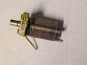
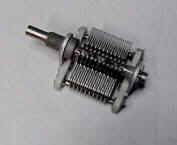
| With some variable caps the shaft containing the movable plates was anchored on both ends of the tuning shaft (dual bearing) while others were pivoted from only one anchorage or bearing location (single bearing). | Obviously the double bearing was much better in this instance, than the single but they were more expensive to purchase and most of us would go out of our way to use what was available, which typically meant --- free. | If your junk box or that of your Elmer or your ham friend's junk box only offered up a single bearing variable but it cost you nothing, there was no doubt at all as to which would be used. | ||
Single bearing variable cap |
Dual bearing variable cap |
Then there were the padder capacitors which got the inductor and variable capacitor within the proper desired range and there were several types available; certain types being better than others for this task. Mica capacitors, which were typically small and rectangular with a wire lead coming from each end of its body, were usually the most available but often had a wide range of tolerance from its marked value. The silver mica type were usually a closer tolerance and more reliable. Builders of Heathkits from that era remember the silver micas as being identifiable in the same rectangular body style but were always in a red case to let you know they were silver mica.
There were also small disk ceramic type capacitors, which always had strange identifying marks and colors on them. These were typically negative coefficient range or positive coefficient range. You see, oscillators also had to contend with the temperature environment in which they operated. That might be affected by the heating and cooling environment of your house, the area of the globe on which the oscillator was expected to operate (and remain "rock solid" in the terms of the day), but also how many heat producing tubes and transformers were to be close by and/or beneath the variable oscillator components. Negative coefficient and positive coefficient capacitors would decrease or increase their capacitive value by a small amount to compensate for what the other components were changing as the temperature varied all over the place. Heat was a bear to deal with and failure to correct for it resulted in a receiver or transmitter that had to be constantly adjusted as the frequency changed. There were even cases where both a positive and a negative coefficient capacitor combination was used to keep the oscillator within as little change window as possible.
|
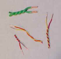
No discussion of oscillator values back in those earlier days would be complete without mentioning the "gimmick capacitor." Often the circuit would need just a very small amount of extra capacity to place the oscillator on the correct range of frequencies, something on the order of just a few picofarads. When the available junk boxes did not yield up a small value manufactured capacitor, the user would take two small pieces of wire and twist them together. Color was not important, wire size was not particularly important, and when one end of each wire was stripped, the gimmick was ready to solder into the spot needed. Just the small capacity between the wires was sufficient to provide that small value capacitor. Also, not only was it easily adjustable (tighter for more capacity, looser for less), but also if something got messed up, another could be easily created and much could be said about the nice cost. Even the poorest ham had odd pieces of wire around their shack. Now temperature stability of the gimmick capacitor, as well as the mechanical stability; that was another story and it was anybody's guess. | |
Sample “gimmick capacitors” Easy
and cheap to make, simple to duplicate, and you determined the value. |
A drifting or moving transmitter VFO caused your signal to move during the QSO and the other station had to track you up or down the band. This was not quite as noticeable when stations were operating AM or amplitude modulation because transmissions were wide and a little frequency change was not as evident. Receiver IFs often had wide bandwidths and quite a bit of frequency excursion on the transmitted end was not always noticed too much. Also, transmissions tended to be long where the operator would throw the T/R switch to begin his transmission, prop his feet up on the desk or the family dog, and wax eloquent for long minutes at a time. So, what if his signal drifted a bit. The ham on the other end only had to lean forward every so often to retune while he was leaning up to get a drink of........... something.......... anyway.
A ham who built a transmitter VFO back in the mid 1900s and wanted to have a rock solid signal had to spend many hours testing and changing component values around in order to hit just the right ones. As mentioned previously, there were even cases where an oscillator circuit sometimes had to have both positive and negative caps because as the temperature changed, the frequencies could reverse their direction of drift.
The components also had to be mounted extra securely because any movement inside or outside the case would cause a slight component value shift with a resulting wobble in frequency. Nothing but the variable rotor plates were allowed to move, and then, only when the change was desired. The Collins Company of Cedar Rapids, Iowa came out with their 75A1, 2, 3, and 4 receivers where they used fixed value capacitors and varied the inductance to change the frequency. This resulted in a nice solid oscillator, which allowed the tuning to be more linear and more accurately "resetable" to a particular frequency. This was highly desired by hams but these pieces of equipment carried a high enough price that it led to flat noses from pressing them against the store display window or slobber on many shirts from drooling over that equipment, wishing they had one. Most of us, however, had to be content with just the dream of ownership and keeping and using our much lesser models of equipment which was often home made.
When SSB (single side-band) came along, more frequency stability was necessary....... even required. A transmitter with a drifting frequency on a SSB signal would quickly turn a copyable ham's voice into one very low or squeaky high and nobody wanted to talk to a station with those problems. To make matters worse, with the advent of transceivers for SSB, one of the advantages was, when you had the other station properly tuned in to where they sounded normal to you, your transmitter was transmitting exactly on that same frequency making for an ideal QSO situation. The trouble with that was, some people prefer to hear another person with a higher or lower pitch than their natural voice. This caused the at least one of the stations to readjust their receiver's dial at the beginning of every new transmission.
Early commercial SSB transceivers had no RIT (receive incremental tuning) so if two transceiver users were operating non-RIT units, as many of them were, Ham A transmits and Ham B alters his transceiver's tuning dial to make him sound abnormally pitched because he liked it that way. When Ham A comes back, he notices Ham B sounds too low pitched so he retunes to make him sound better. When it goes back to Ham B he, again, shifts his tuning knob to account for A's drift and/or voice pitch. This leads to the two stations "leap-frogging" up the band, often running into another QSO that was originally sufficiently far away in frequency.
Part of this problem was cleverly cured with the addition of RIT (receive incremental tuning) which allowed a station to readjust his receiver frequency to make it sound correct for him but NOT moving the transmit frequency to cause the "leap-frogging" effect. Many of the first RITs were homebrewed modifications added to a commercial transceiver for the convenience of the user but now, you'd be hard pressed to find any commercial transceiver without this feature.
The Swan Company was one of the early manufacturers to offer a commercial SSB transceiver. They were compact, relatively easy to operate, priced within the range of many hams, and offered a quick and easy way for the growing ham population to get on this new mode which offered more power per watt and ease of increasing that power with a linear amplifier. Swan sold a lot of their transceivers in single band, tri-band, and all band models. As I recall their manufacturing period preceded the WARC frequency bands, in the mid 1970s, where hams were given additional frequencies on 30, 17, and 12 meters so few, if any, of the Swan units allow operation on those additional bands. Swan transceivers did have a reputation for a VFO that did not like to stay in one spot during an entire QSO. Swans often drifted and drifted rather badly. Swan probably rued the day when they assigned the model number "350" to one of their popular all-band SSB transceivers because its failure to hold to an assigned frequency provided its notorious nickname. Almost all hams, during those years, referred to that unit as the "Swan Three Drifty" or the “Drifty Three Fifty.”
Other transceivers came along commercially and many also suffered from bad VFO drift. The Eico 753 and several of the National transceivers seemed to have that reputation. Drake did better and I recall fewer complaints about their lack of frequency stability. The astute reader will note that no mention was made of the currently well-known Japanese transceivers since this was prior to the major introduction of ham radios manufactured in the Orient.
Many of these frequency stability problems went away when manufacturers began to use a digital type circuit for their variable frequency oscillators, both for receive and transmit use. By taking a crystal circuit that can be made remarkably solid with no perceptible movement, digital circuitry can divide and multiply that initial crystal frequency and turn it into any new frequency that is required in the equipment. If the crystal oscillator remains on frequency, the frequencies generated up and down from that base are also solid. Using digital electronics to provide the frequency determination allowed manufacturers to use digital encoders to smoothly and linearly increment or decrement the radio's frequency. No longer were variable capacitors required to provide the user with a changeable frequency. No longer were pieces of ham equipment required to be “built like a battleship” and “heavier than a tank” to maintain the rigid mechanical necessities of the coil/capacitor component type variable oscillator. As an additional benefit, the digital operation of the frequency allowed the addition of computerized connections to the equipment. The equipment could be tuned remotely and the actual receive and/or transmit frequencies could be read out to a computer to tie additional equipment to the original piece. Also now computerized logbooks could record the actual frequency and mode being used. It opened up a myriad of possibilities for equipment manufacturers and these companies have not disappointed us.
The problem of the frequency stability of ham equipment has certainly come far from those early days of home brewed radios. Unfortunately, the mental stability displayed on the ham bands, as previously mentioned had a much further path to tread.... and I fear that it's not even on the schedule for improvement.
Still, I would hate to go back to the radios of yesterday. It was fun back then but I enjoy my computer-attached and controlled radios of today. I don't miss those days of telling a friend that I'll meet them somewhere between 7220KC and 7230KC. Now, when a station tells another, "could you meet me down on USB on 14.265.7?" both can place their radios on that frequency. Even though they are using different models, from different companies, from different countries, both those stations will be exactly on the same frequency and not need to search and tune for the other. We've come a long.... LONG way.
Thank goodness!
On to Volume 50 (pending)
Page visited 900 times![]() Return to the Home Page
Return to the Home Page