K5LAD - 50+ Years of Ham Radio Memories
Volume XXXV
AC/DC Comments SpanningSeveral Decades
By Jim Pickett – K5LAD
Search keywords: rectifier, diode, selenium, mercury-vapor
There's a topic that I have not adequately covered in my various articles and I plan to rectify that situation. The topic is, early day diodes and rectifiers.
Relative newcomers to the radio hobby, especially those who build or repair their own radio equipment, usually have a large drawer filled with those black, bullet-shaped objects called silicon diodes. They're cheap to obtain and can be fit into many small spaces. To many hams, perhaps those who never recall seeing a real-live telephone without a rotary dial, these diodes have always been around.
Many really old-timers will remember the older vacuum rectifier tubes, which came in various sizes from the squatty little 7-pin 6AL5, to a taller 7-pin 6X5, up to an octal-based 5Y3, or the taller 8-pin 5U4GB or 5R4GB. Hams who remember seeing stations in the 1940s and 1950s, and even later, might remember the 816 and 866 mercury-vapor high voltage rectifier tubes. When in use, these mercury-vapor tubes glowed a bright and eerie blue or purple color and as more current was drawn through them, the glow varied in its brightness. I remember, well, the station of my Elmer, Ike - W5IER in Sand Springs, who had a home-built 813 AM transmitter with a big plate modulator. The power supply used those mercury-vapor tubes and was located on the floor underneath the operating table. I remember being fascinated with the purple glow that followed the modulation pattern. On voice peaks the purple glow was the brightest and I could hear the laminations of the modulation transformer as they vibrated in synchronization with his voice. Dr. Frankenstein's laboratory was a simple toy shop compared to that ham station and as a wide-eyed teen, I was fascinated.
When any new electronics project was planned, especially if it was to be completed using ‘junk box parts’ instead of store-bought parts, the builder often first found a suitable transformer for the project. Depending on the power rating and the availability of a secondary center-tap on the transformer, that would help to determine what type of rectifier tube would be used, but one item was already decided at the outset, it would be built using a tube-type rectifier because that was what was available during that time.
As time marched on, it was a wonderful day, and an amazing step forward when many of the smaller vacuum tube rectifiers were replaced with a new device called a selenium rectifier. The selenium rectifiers had some real advantages, plus a few negative sides but for the more simple needs of a radio circuit, if they just wanted to convert a bit of AC to a DC voltage, the selenium rectifier was a nice item to use.
Selenium rectifiers came in many sizes, shapes, configurations, and colors. Some that I saw were as small as ½" square by various widths up to about 6" square with large, wide-spaced plates. There may have been larger and smaller versions but I was not in positions to see that many different varieties. I saw them with both square and round plates in the electronics projects I was around. They were often painted and they came in all colors.
They often had only two terminals (AC in DC out) when used as a half-wave rectifier. There were many with 4 terminals (2 for AC in, 1 +DC, and 1 –DC output) and were configured as a full-wave bridge. There were others with 3 terminals (2 for AC in, 1 DC out) with the other polarity for the DC being provided elsewhere, such as the center tap of the AC secondary on the transformer. I imagine there were others that I didn’t see that were even in different configurations.
On the pro side, these rectifiers were smaller and did not require a filament supply voltage. For that reason, the unit they were in usually ran a good bit cooler. Their construction allowed them to be mounted more easily on a chassis, which often lead to a more attractive looking piece of equipment. This also allowed for less space allotted for the whole power supply circuit.
On the con side, these rectifiers were limited in both the voltage and current for which they could be used. A selenium rectifier also had quite a noticeable voltage drop so when they were later replaced by small silicon diodes, that had a much smaller drop, the user had to account for an increased voltage output. Also, when a selenium rectifier failed, it was usually a short that caused them to get very hot. Some actually heated to the point of setting the rectifier piece aflame.
The smoke that poured out of a burned up selenium rectifier was absolutely terrible. Thick, acrid, smoke which clung to your clothes and in the radio where it had been installed, and it seemed to attach itself and linger in one's nose for hours. When it first destroyed itself, you almost felt you could cut the smoke from the air and you thought, at first, that you were almost chewing the smoke. It was terrible! The odor was most closely related to the smell of rotten eggs. If you want to see an old timer ham make a funny, scrunched-up face, just ask them if they were ever around a selenium rectifier that burned up.
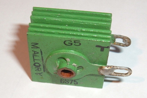
The selenium rectifier stack could always be easily identified since it was constructed of numerous, often square, plates stacked on a common stack with each plate separated from the others with an air space. They resembled a variable capacitor but there was no part that moved, as the plates were stationary. The spacing helped to determine the heat dissipation capabilities of the unit so some were wide-spaced and others were fairly narrowly spaced.
Many of the TV sets manufactured during the 50s and 60s used selenium rectifiers but few ham receivers did and I don't recall any transmitters using them for their higher-powered requirements. The voltage and current requirements for ham equipment was just a bit above the abilities of these devices but quite a few of these were used for constructing bias supplies in ham transmitters. If you dig back through some of the older amateur radio books and magazines you can find examples of these old rectifiers.
They could be placed in series to increase the voltage capability of the group but when one failed it often took the whole string out with it. Also, since the voltage drop was a bit high, it tended to eat away at much of the user's voltage that was available for a project. They were not difficult to mount since a single long screw usually held the device securely to the chassis wall, which even provided some heat dissipation capabilities.
A lot of the older Heathkits used selenium rectifiers for lower voltage rectification requirements, particularly in their test equipment, TV receivers, and smaller audio equipment. If you stumble across an old Heath piece of equipment, or any old piece of radio equipment from the 50s to 60s era, particularly if it emits a bad smell, suspect a selenium rectifier problem.
When silicon diodes became more popular in the mid to late 60s and early 70s, one of the first things an electronics experimenter would do was to replace the selenium stack with the smaller silicon diodes. The "cheap and dirty" way was to just wire the silicon diodes across the selenium leads (plus to plus and minus to minus) and leave the older device in as mounting hardware. This was often done successfully but because of the lower voltage drop of the new diodes, the voltage was often a bit too high for the equipment. It might work for a while but was sometimes a disaster just waiting to happen.
Also, to leave the old selenium rectifier in the circuit, it retained its ability to burn up, releasing the pungent smell previously mentioned. It's a bit like keeping the family's pet skunk living under the back porch, because, "we're pretty sure it doesn't have the ability to squirt stink any more." Many things in life are a gamble and this paragraph lists two of them.
Hams now a days who still have their repair and building skills hats, will generally always use a silicon rectifier, or a series of them, any time a rectification task is required. Even high-powered, tube-type amplifiers requiring several thousand volts of DC output will use a string of silicon diodes in series making a nice and compact power supply. They do miss the excitement of the glowing mercury vapor high voltage rectifiers and the stench of burning or burned-up selenium rectifiers in their hamshacks, however. Let’s see………… those were called the "Good ‘Ole Days" weren’t they?
Page visited 478 times![]() Return to the Home Page
Return to the Home Page