ICOM IC-720/A
This page will continued be refined and updated as information becomes available. If you are looking for the latest updated files, they're at the bottom of the page.
BACKGROUND
The enclosed software was written by Julian Arambarri in Spain. Julian does not have a ham call and only uses the program he wrote for receiving General Coverage signals. That's pretty nice for him to have added all the ham features which he currently does not use. He did say, however, that he might be interested later in getting a ham license. He would certainly be an asset to our hobby. Several months ago, on the 720 Reflector, there was a discussion about controlling the IC-720 via computer. The following email entry was from Thierry - F6ITQ:
Hello,Several pins of the IC 720 rear panel ACC socket can be used to control
some functions of the trx like mode, band, frequency and VFO selection
with a specific protocol. 4 pins are used for the protocol and 4 for the
data exchange.
The protocol of the data exchange is described in QST of july 1984 pages
34 to 38. The article describes how to pilot the trx with a centronics
parallel port of a HP 86 computer progammed in basic language and a
specific interface made of TTL ICs. A flowchart summarizing describes
the program structure. For sure a updated interface can be designed with
a PIC microcontroller.
If needed, I can send you a copy of the scanned document.
73 from Thierry - F6ITQ
Julian answered him:
Dear Thierry!
I had news about this article but it is not to easy to find it
for me . if you are able
to send me this article it wil be great for me.
best regards
julian arambarri echaluce
C/ Matias nieto serrano nº 10 6 -D
34004 PALENCIA
(spain)
A later message from Julian in late June, 2003 read as follows:
From: "julian arambarri" <jjulian@jazzfree.com>
To: <IC720@yahoogroups.com>
Sent: Saturday, June 28, 2003 2:29 AM
Subject: [IC720] parallel interface
> Hello !
>
> I am julian from spain i have a ic-720 and i am very happy but the
problem is that i want to connect it with my computer .we have 7 signals DBC
RC DV RT and four DB1-4 maybe anyone has information about this hardware
protocoll because i can not find information in internet about this.
best regards
Bill, WD8ARZ answered him back:
The Icom IC720 and IC720A do not have a computer interface, such as a serial
or parallel port connection. Never has. You can not change frequency, mode
or other radio function with a computer on this radio.
I and others looked in to this a long long time ago. The best I could come
up with was a mod I had used on a yYaesu two meter radio that would change
the vfo oscillator frequency so you could 'scan' the band. Never felt this
was worth while on this hf radio due to no squelch. I did add a squelch to
the 720 I have, but it is not a good hf squelch and opens on pops and static
making scanning almost useless except on a very quite band.
You might be confused about a computer interface on this radio by articles
that allow you to convert audio signals from 'any' radio to a digital
format, such as fax, rtty, psk etc etc. There is for example a cw program
that will not only receive cw out the audio jack and display it on a
computer screen, but with a simple transistor interface key the rig for
sending cw typed on the keyboard. But this applies to any transceiver, and
not just the 720.
Hope the radio is working for you other wise.
73 from Bill - WD8ARZ
Bill amended his comments with the following message:
Darn, I made a major error on the a rush email just prior to rushing off to
work!!!
It was the Yaesu FT-301D that doesn't have a serial or parallel port, and
that was the rig I was considering for a oscillator scanner mod that I had
done on a two meter rig!
The Icom 720/A does have some limited function to a computer interface, yes
it does.
Now that I have my rigs straight in my mind, I recall having made a box plug
in for the rear interface. It had toggles switches mounted with some
circuitry that allowed stepping bands, inputting frequency, changing vfo and
mode. The next step was for a computer interface to automate some of that.
Never got to that next phase .... hi hi Still have the rig and the
interface box though.
Man, this brings back the memories, but a huge apology for my memory being
so wrong on my last email!!!!
73 from Bill - WD8ARZ
On or about August 10, 2003, Julian announced that he had written controlling software for the IC-720 and 720A and offered to provide it free to anyone who was interested. Here follows his message:
hello friends!i have done it i have made a software based in c++ builder
,also i made a small interface with the centronics port in my PC and now i
am able to controll almost all functions in my IC-720 .I got the idea
from a 1984 qst article in this article explains how to connect a ic-720
paralell bus .my hardware is different that the article it is very simple
but it runs very well.in my email you will see the software if are able to
controll the ic-720 you can controll the soft.
Best regards
Several days later, on August 13, Julian sent another message out to the 720 Reflector. This message said:
HelloI am julian again i am drawing the circuit for the interface it is very
simple only it use a 74ls245 and a one transistor if you want to transmit.
The interface is connected to the paralell port and it gets the power form
the ic-720 . about the soft it runs in windows 98 and windows xp and it
not deppends if you pc is faster or not because i use a API functions for
the protocoll .this soft wil be freware for all the IC-720's menbers but i
have problems if i want to send it by email because the file is too big
because i need the runtimes dll.
best regards
I immediately wrote him to get copies, even though I live in Oklahoma and was currently on an extended trip to California. Julian sent me the first copies, and within days sent along the schematic for the hardware interface. The message below was with this hardware interface:
>From: "julian arambarri" <jjulian@jazzfree.com>> > Date: 2003/08/17 Sun PM 03:43:03 EDT
> > Subject: hardware schematics
> > hello
> > Here you have the circuit for the interface, i am electronic engineer
>and i think this is the simplest hardware that i made.it cost arround 6?
> > or 6 $ and it only uses a 74ls245 or 74HC245 it is the same .i include
> > a picture from my prototipe that it is running 100% and i very happy.
> > in my prototipe i use a extension cable for the centronics port one part
>its a db25 male and the other is a db25 female but it is only a idea.
> > the conexion to the molex conector i use a 12x0.25 + ground cable an
>i connect the ground to gnd.
> > BEST REGARDS

Once I had returned home to Oklahoma I unzipped the files and ran Julian's program, even though I had not built the interface. It was an impressive piece of software and I told him so and recommended a few suggestions if he so chose to make them.
Today, Aug. 31, I received the updated software from Julian with the request that I test it and distribute it to those who had expressed an interest.
Below is a copy of an email I sent to Brian in New Zealand concerning obtaining the 24pin Molex plug required for the interface:
On 29 Aug 2003 at 9:21, Brian Heywood wrote:> Hi group,
> I cannot source a Molex 24 pin plug here in New Zealand.
> Is there someone able to source the above item and mail to me ?
> 73
> Brian Heywood, ZL1IE
-------------------------------------------------------------------------------------------------
Hi Brian --
I was just looking for the same thing several days ago..... I'm wanting to
build Julian's parallel port interface and use his software with my 720A.
I finally found a package which had both male and female 24-pin Molex
connectors as well as the wire end connectors to go with them. The
package was labeled Molex - Waldom and had the part number 1625-24PRT.
Reading from the back of the bubble package it has the following pieces
included:
1 Pc. Plug 03-06-2241
1 Pc. Receptacle 03-06-1241
27 Pc. Female terminal 02-06-1103
27 Pc. Male terminal 02-06-2103
Of course, also, the pins are not the regular .093" Molex ones but these are the .062" and the package says these terminals are for
"#24 thru #18 wire range." The place I got the is an electronics parts house in Tulsa called Affiliated Electronics. The cost for the
package, which included all of the above pieces, was $10.95. I don't get to this place very often but if you are unable to track
anything down using the parts numbers above, perhaps I can get you one or two, as long as you're not in a big hurry. I also got
the IC for Julian's interface, although I'm not sure if what I got will work. His info called for a single 74LS245. Affiliated had a
54ALS245 for $1.10. I'm not worried about the 54 number but that extra A in the number is new to me. I hope it works.
I hope this is some help for you.
73, Jim - K5LAD
================================================================
INSTRUCTIONS:
This information from Julian (dated Aug. 31):this soft is complet you can scan in two diferents ways if you are in ham mode it scans only the band and it changes
scanup or scandown and if you are general cover scans all the time untill the maximun or minimun.
also if you are in general cover you can edit the frecuency and then push enter.
in this version you will have a lot of memories you can made comments and add news or recover one and also you can
delete one the memories are in the file memories.txt the structure of the memories are oklahoma=703000 but you can use
the soft.
i need to help because for me is very dificult to make the help file maybe anyone can help me .this person has to edit the file
help.txt with the instructions of this soft in english of course .first i needs to test all the functions and after edit the file
help.txt with the worpad and save in the interface directory.and after send this file to everybody. please help me because
i have a lot of work in my factory and i dont have free time.(my wife is not very happy with this project).
be carefully if you are using the soft dont move the dial because the ic-720 will have information from two diferents ways.
and you will a unusual caracters.dont problem disconnect the ic-720 for 30 seconds and restart the ic-720.
before you connect the interface disconect the ic-720 and pc .
==============================================================
As I understand what he is saying --- when you are in the HAM mode you can click on SC-DN or SC-UP to change the direction of the scan which is only within the band in which you are in. Evidently, when in General Coverage mode the scan starts where you originally enter a frequency and just keeps going. (I suspect that as it crosses past a MHz range that it will automatically step the band switch.)
NOTE: I have written Julian about it but, to me, the SC-UP and SC-DN plus the HAM and G. COV buttons are reversed from what I would expect. Perhaps Europeans use this convention but it seems backwards to me.
When you click on the MEM button you gain access to memories ranges, i.e., 20M CW -- 14.000, 80M AM SSB - 3.7900, etc. The colored boxes to the right of this information allow you to ADD (add another entry to the list), RECOVER (tell the 720 to jump to that frequency and display it above the tuning knob), DELETE (delete an entry in the list -- the one which is currently highlighted, and EXIT MEM (close the list). NOTE: To add a line to this list, move the frequency displayed to the frequency you want on the list, type in the left column word that you want (up to 10 characters), then click on ADD. It will be added to the end of the list. It is also possible to add an entry by going to the folder containing the program and locate a file called "memories.txt." You can open that file with Notepad or a similar text editor program and edit the list the way you want it. I have added lines of "---------------------" hyphens to separate each ham band on my list.
The help file which is displayed when you click on the HELP button is bringing up a text file called, "help.txt" which is also located in the program's folder. I plan to do some work on this one and will place my file on the web page when it is completed.
Julian also cautions the user to not turn the tuning dial on the IC-720/A which the interface is hooked up and the program is running as strange characters will suddenly display. As I read it, he is saying that if this happens you should disconnect the transceiver for 30 seconds and then reconnect. I'm not certain if he means you must physically remove the connector from the 720 or just to power the unit off for that period of time. Once I have my interface built and working I can get a better idea about this.
Additional information added 9/4/03:
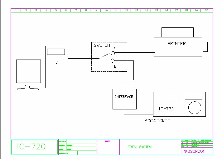
Julian has sent me another file to repair the reversed condition of the buttons and also adds the 17 M and 12 M bands. Note that to move to a different ham band the two buttons to the far right are labeled UP and DOWN and that is to move up and down the list of bands. He also sent me another jpg showing how he has his system set up. This file is called "ic720system.jpg" and is downloaded by itself or is now included in "720SoftwareV3.zip"
I have uploaded the new file to make the above corrections and it all of this is found in a new "interface1" file. You only need to unzip the new interface1.zip file and it should overwrite the older files. Note, in particular, that Julian has made a new "Memories.txt" file which includes the new 17M and 12M bands plus several memories which are Julian's. If you want to retain your current memories you should rename your current Memories.txt file since the new one will overwrite it.
When you are scanning within a ham band, the program knows the limits of the band and will only scan within those limits. The SC-DN and SC-UP buttons have been changed so they are now correct for changing the direction of the scan. You will note a large red box labeled "STOP" in the upper right-hand area of the display and it's job should be fairly obvious.
Julian noted to me that this was the "last file." I don't know if he is backing away from any programming on it since he had mentioned that his wife was a bit unhappy about all the time he was spending on it. His English is quite good but he may have been saying that this is the "latest" file. He has been very receptive to my suggestions, however.
As mentioned above, to get the latest version you only need to download interface1.zip and the file called "ic720system.jpg." I have updated the combination file called "720SoftwareV3.zip"
================================================================
Here are the downloadable files.
The original files from Julian are called: interface1.zip, interface2.zip, and interface3.zip.
The hardware interface is ic-720 circuit and shows below as ic-720.jpg. The new system configuration file is ic720system.jpg.
I have also zipped those 5 files together in a file called 720SoftwareV3.zip if you have a nice fast broadband downloading capability.
Note there is no help file as yet but I hope to generate one (see above).
interface1.zip <--------- This is the new one with a color 720 interface
720SoftwareV3.zip (New version with all 5 files - including file with color interface)
Jim - K5LAD ---- If you'd
The page was updated on 02/04/04 10:31 PM