|
Take
it all in, then filter out
what
you don’t need or want
An
oversimplified view of roofing filters
By Jim
Pickett - K5LAD
NOTE: This
article was originally written for inclusion in the TARC (Tulsa Amateur Radio Club)
Newsletter
There have been millions
of words written about the subject of filters used in typical ham applications. A quick Google search for filters in ham radio
would probably offer millions of hits and many would be quite involved, complete with
formulas, charts, and diagrams explaining them in great detail. This article is an oversimplified look at filters
to, perhaps, help a newcomer to the hobby.
The value of a
filter in a receiver has always been known. Filters can be made of tuned circuits using
inductors and capacitors, with crystals, and by mechanical means. Even newer is the use of electronic circuitry to
convert an analog signal to a digital one and apply “electronics magic” to deal
with the signal. Sometimes it is desirable to
have a very broadly tuned filter that covers a wide range of frequencies and sometimes it
is preferred for them to be very narrow. For
instance, a 2 meter VHF receiver front end might want all or most of the frequencies
within that band to pass but to exclude, or at least attenuate, the frequencies in the VHF
commercial bands several MHz away. A very
tight filter in the IF of a receiver would want to pass a SSB audio signal of
approximately 300-3000 Hz but exclude a similar signal located just a few KHzs away, and a
CW filter might want to exclude a closeby signal as near as 100-200 Hz away. The advantage of tighter filters is the
exclusion of very closeby signals, the disadvantage is, the tighter the filter, the more
difficult it is to tune and, in the case of voice signals, the less understandable is the
person speaking.
Imagine being
crowded into a room with many, many other people. Ideally
you want to build walls around yourself to define "your space" from all others
so you could concentrate on the one person you were speaking with. If you build your walls out too far, so that you
have plenty of space to move around in, you'll be into someone else's space. When those others talk, their sound is a bother to
you. Should you build your walls too closely,
you might exclude many of those others but you feel "jammed up."
With the advent of
new DSP (digital signal processing) circuitry it's now possible to build higher walls but
still make your space of a comfortable size. The
DSP circuits can look out over the sea of faces and identify just the one face it wants to
see (or actually, to hear). If only the DSP
could see fewer faces originally, the easier it would be to zero in on just the one they
want.
Enter, the roofing
filter to this picture and example. The
current roofing filters being used are made with crystals cut to essentially the same
frequencies that allow signals within that small area to pass to the exclusion of all
others around it. It says to the DSP,
"here, just look at these few signals and do your processing on them. Let's forget about all those others around the
one you want." The roofing filter limits
the range of signals fed to the DSP for processing.
An additional
benefit of the roofing filter is to protect or, perhaps a better term would be, to
‘shelter’ the AGC of the receiver. The
AGC (Automatic Gain Control) is the circuit that protects your ears when a strong station
or stations suddenly appears. The AGC is
‘looking’ at the entire receiver IF passband and if a strong station appears in
the passband, it knocks the gain down and in doing this it protects your ears from the
blasting audio. A fringe benefit (and a
distinct disadvantage) is that it also lowers the gain on the weak station you’re
really trying to hear. The roofing filter
makes the passband seen by the AGC much less (narrower) and in doing so, the weak station
is not minimized because of the presence of the strong station nearby. If the AGC cannot see (or hear) signals nearby in
the passband it does not need to use part of its resources to attempt to deal with it. As far as the AGC is concerned, if it’s
outside of the roofing filter’s bandwidth, it does not exist.
Imagine being in a
room with quite a few people and trying to listen to one person but the piano is playing
loudly across the room. If you could pull the
walls of the room in but the piano would remain in its original location then the piano is
on the outside of the wall and does not bother you. In
fact, the new wall might even make it so you don’t hear the piano at all. The roofing filter isolates the sounds coming from
nearby signal and makes it like the signals are not even there, just as though the piano
is not even in the room.
Several of the
older commercial transceivers are being modified to include a roofing filter in their IF
string to improve their selectivity. There
are also a few of the newer rigs being built "from scratch" with roofing filters
as a part of their design. My favorite is the
K3 transceiver from Elecraft, shown in the picture below.
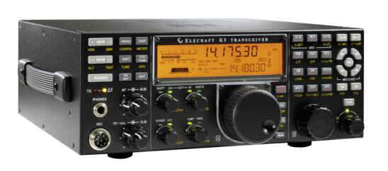
This transceiver has now
been available for about 2 years and has received rave reviews. It comes with a 2.7 KHz roofing filter which is
very good for all bands and modes. In
addition, the transceiver has provisions for adding up to 4 additional crystal roofing
filters in widths like: 200 Hz, 400 Hz, 500
Hz, 1.8 MHz, 2.1 MHz, 6 MHz, and 13 MHz. The
narrowest filters are typically for CW and other digital modes, the widest for AM and FM
mode and the ones in the middle are more desirable for SSB. Remember that the narrower the filter, the fewer
interfering station you'll be hearing.
It might seem
then, that if you always used a very narrow, i.e., 200 Hz filter then you could easily
exclude all the interfering stations leaving only the one currently holding your interest. Unfortunately, that is not always the case. Listening to a SSB signal with a very narrow
roofing filter would make it impossible to understand.
I picture a person in an elevator whose lips have somehow gotten squeezed together
by the closing elevator doors. They try to
speak but they are not understandable due to the severe restriction.
To quickly
demonstrate the value of a roofing filter, I used my own K3 with the 2.7 KHz filter, and
using an LP-PAN panadapter to demonstrate the signals spread within a band, I made the
following screen shot of the PowerSDR software.
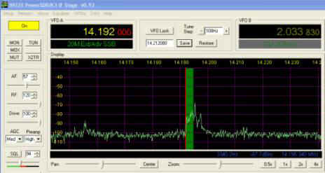
The receiver is
tuned to 14.192 MHz and there were several signals on the band. I was listening to the one on 14.192 but there was
another, even stronger signal at about 14.195 Mhz. Ordinarily,
on a typical receiver it would have been very difficult, if not impossible for me to hear
the station on .192 due to the stronger station nearby.
This other annotated version of the same screenshot, explains the value of the
roofing filter in my K3. The picture should
explain it better graphically than I could in words.
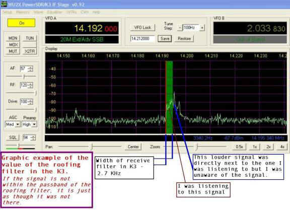
Whether
you’re operating during a contest, where the panadapter would have vertical blips of
signals strung all the way across on both the left and right side of the green bar above,
or during a normal time with fewer signals, the receiver is only responding to the signals
within that green bar. It doesn’t ever
know (or care) that others exist.
If you’re in
the market for a new radio, you would be ahead of the game to look at one with a roofing
filter. Roofing filters are the wave of the
future and are a highly recommended feature. Why
should we listen to everybody when you only want to hear just the one?
========================================================================
Created August 23, 2007
Page visited 902 times
Last updated 04/02/2010 22:54:23 PM
 Back to K5LAD's Assorted Ham Stuff Menu Back to K5LAD's Assorted Ham Stuff Menu
 Back to Home Page Back to Home Page
|