Building K5LAD's 4-1000A Amplifier
I built this amplifier back in my younger days, back in the early 1970s. A check of my logbook shows that my first contact using the amplifier was with Gene - K5NYT in Tulsa on 3905 KHz on March 31, 1973. Since that time, I've made many contacts using it and this amplifier has always been a real benefit for my ham station. On numerous occasions, I've gotten requests from other hams, asking for a copy of the schematic or some other detail on my amplifier. The truth is, when I originally built the amplifier, I had no "official" schematic and different sections were on various scraps of paper. I always kept the scraps together in a folder but it was far from being an organized documentation package. Different sections of the circuit were taken from different places. When I found a part of a circuit I liked on some other published amplifier circuit, I borrowed it and incorporated it in my amplifier.
Finally, in 2008, some 35 years after building the amplifier, I decided to put together the scraps and get some sort of organization to my documentation. Using Microsoft Paint, during times of poor TV shows (and there were MANY) I drew up the schematics of the power supply section, the control section and the actual amplifier. I've tried to identify different pieces used in the project, often from the original bills of sale from the piece which I had also saved in the documentation folder. Some, however, are not identified completely, by either a commercial nomenclature or an actual value since I don't have that information available. If this amplifier ever breaks down, I'll get back inside and write down some of those unknowns. The problem is, however, this amplifier has many of the features of the Eveready bunny and just keeps going and going and going. When I built the amplifier originally, I did not deliberately build it for quick and easy disassembly so I've never decided to just sit down and take it apart to identify the innards of the beast. Some day, perhaps, but that activity is certainly not scheduled. If someone wanted to duplicate some of this amplifier, I think there is enough identified that it would not leave you too far out in left field. In particular, I'd like to be able to identify the values of the tuned circuit in the switched input of the amplifier but that's probably a several hour project and just not one I'm interesting in pursuing. Perhaps if I ever retire I'll have some time to do that............ Oh, oooops, I'm already retired. Oh well.........
First is the schematic of the amplifier. The amplifier cabinet was constructed from aluminum angle stock which was tapped to allow the shell of the amplifier to be attached with 10/32" by 3/4" binder head screws. The front panel was constructed from a commercial piece which was Bud PA-1109 – Aluminum Panel (15 ¾”x19”x1/8”) - Light gray textured. After all of the holes were drilled and machined into the front panel, the lettering was engraved into the aluminum and black paint placed in the engraved letters. The front panel was then belt-sanded to give it a nice smooth grain, then it was clear anodized to protect the surface. Now, after 35 years the front panel still looks as nice as it did the day I made the first contact with it. I was fortunate enough to have a good ham friend who owned a specialty machining shop and he took care of the engraving, sanding, and anodizing tasks. I don't recall what I paid for this service but it was worth every penny.
The inner chassis, made from a Bud chassis – Bud AC-1428 - Chassis (15”x17”x4”), had all the holes sealed and the squirrel-cage blower blew directly into this sealed unit. The chassis was totally pressurized and the only way the air could escape was through the Eimac air socket, past the tube filament pins to keep them cool, then with the help of the Pyrex tube chimney, past the tube's outer envelope, then past the aluminum-finned tube cap and out the top of the chimney and finally, out the top of amplifier via a nice round chrome 5" speaker cover. Even the rocker switches in the front were sealed so air could not escape around them. As I recall, I used quite a bit of RTV to seal every little nook and cranny.
The amplifier schematic has most of the components identified. The exception is in the input tuned circuit. Only one band is shown and even then, I did not have the values written down, at least on any note I had saved. The three larger meters used were a cheaper Philmore 0-1 ma meters but were available at my ham store when I built the amplifier, really looked nice, and an especially nice thing -- they all matched. The scales were hand drawn to match the new scales but I have recently found a program which allows the user to make a really nice, customized and colorized scales so that project is on my list. As closely as I can recall, here's a list of parts used in the amplifier section Click on this link. Note that there are some prices beside some of the pieces and it should be noted that these come from the scraps of paper and the original bills. Remember that this was in the early 1970s and that was back when you were buying gasoline for less than 99 cents a gallon............ assuming that the reader was even born during this time. Ah, the good ole days.... where have they gone???????
Click to download 4-1000A amplifier schematic
Note that the amplifier has a smaller output meter with a potentiometer adjustment just for maximum and quickly tuning the amplifier. The amplifier also has a built-in ALC circuit to allow a negative-going voltage back to any transceiver which needs that. I could not find any scraps of paper with an ALC circuit shown so that's another one that I'll need to reverse engineer whenever I open the amplifier up. If you're using one of the typical ham 100 watt output transceivers, you don't need to worry about overdriving this amplifier.
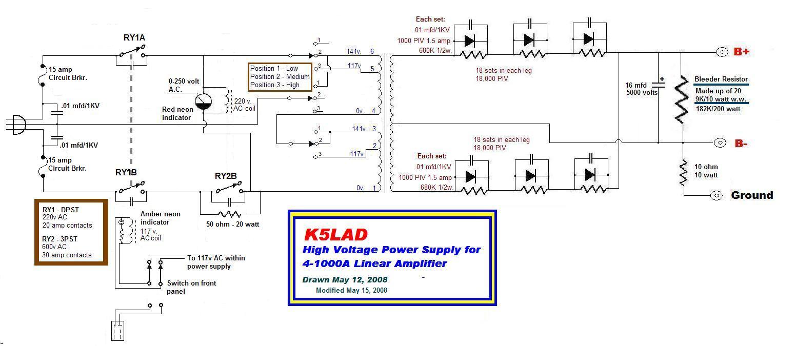
Here's the power supply schematic:
A list of parts for the power supply is also available by clicking this link. I wish I could also tell the reader where I got the parts I used so they might be able to find the same for themselves but it's just been too long since I found these parts.
Click to download 4-1000A power supply schematic
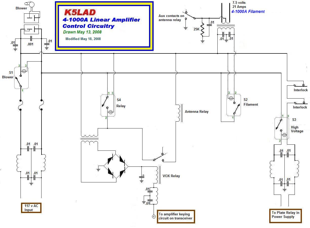
And here's the wiring used to control both the amplifier and the power supply:
Click to download 4-1000A control circuit schematic
The four switches, used in the control circuit are SPDT rocker switches with a translucent body and a neon bulb and series resistor behind it. When the switch is in the ON position, the rocker switch body is lighted. This makes a nice feature.
The FIL. switch is wired so that it cannot apply power to the tube filament unless the BLOWER switch is also on. Since the tube filament takes 7.5 volts at 21 amps, that's a lot of heat to dissipate, even if the high voltage is turned off. The 4-1000A has an instant-on filament so there is no need to have a delay between powering the filament and applying the high voltage.
The H.V. switch controls the 117 volt AC voltage going to the power supply cabinet through the Remote/Local switch on the front of the power supply box. With current cabling, the power supply box can be located 8 to 10 feet away from the amplifier, the user has complete control from the front of the amplifier panel.
The RELAY switch could also be called a "Stand-by" switch since it allows the amplifier to be fully powered up, both filament and high voltage, but with this switch in the off position, the transceiver will bypass the amplifier and feed through without amplification. In this stand-by position, the tube is biased off to draw minimum plate current with no drive.
The pictures, and the descriptions shown below them, are from the power supply section. I'd like to say that I build all of my equipment so that it looks beautiful and could be used as an example for all, however, it's just "ain't so." I even considered leaving out the pictures of my power supply construction so you might think that since it works so well, it must be a picture of perfection. Ha! It is what it is and it works well and every time so, what the heck!?!
|
|
|
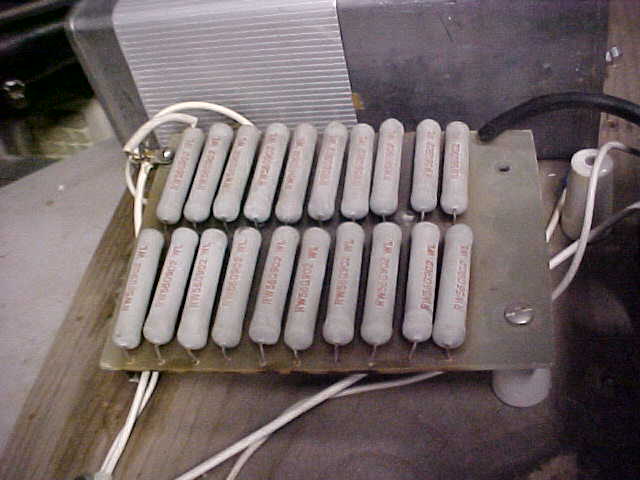
This is the PC board which holds the series
bleeder resistors. It is made up of 20 - 9K/10 watt resistors in series. Measured
resistance is 182,000 ohm at what would be 200 watts. The board these are on is good
fiberglass material with solder tabs left on the board and the rest was removed. The
copper materials not needed were removed with a Dremel tool leaving only the solder tabs.
The board measures 6 1/2" x 4 3/4". |
This shows the underside of the PC bleeder resistor board. When the fan failed, the board got very, very hot. Since the solder pads did not loosen, I chose to keep using it. The fan now blows directly over these resistors when in use. The board was originally a solid piece and the material which was not part of a solder pad was removed with a Dremel tool. Click here to see the details on the bleeder resistor board. |
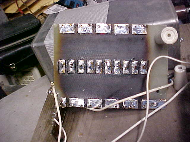
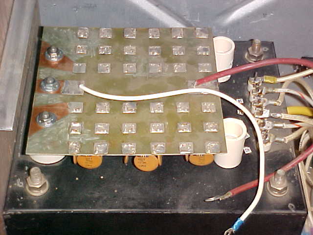
This is the top side of the diode string. There are a total of 18 sets of components in each side. Each set consists of a 1000 PIV 1.5 amp silicon diode, a 680K ohm 1/2 watt resistor, and a .01 capacitor. In recent years I've read that there is less need to balance each diode and protect each diode with a capacitor but this was built in the early 70s when most power supplies recommended these precautions. |
 |
 |
|
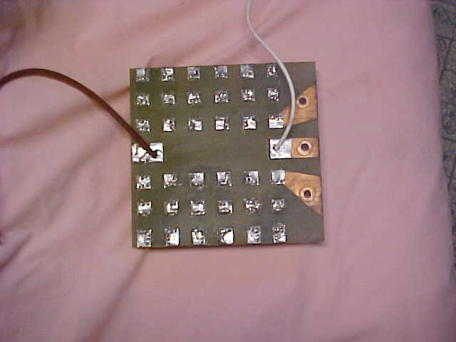
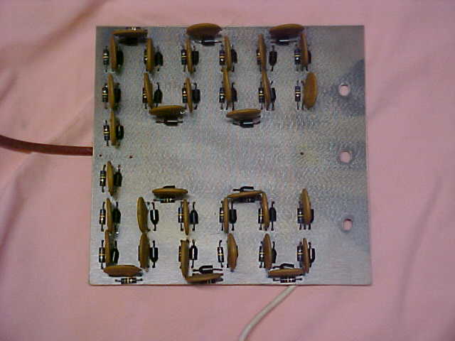
The diode string board from the solder pad side. The three larger pads, shown here on the right, are mounted directly on the high voltage secondary insulators on the power transformer. The white wire carries the minus voltage and the red wire carries the plus voltage out of the diode string. |
The diode string board shown here as a block diagram. Each yellow rectangle represents a set of 1 diode, 1 balancing resistor, and 1 capacitor. |
Here the diode string board is securely mounted on the insulators bringing the high voltage secondary out of the transformer. This gives an absolutely solid mount to the board. The two white circular pieces on the right side of the board are pieces of 1" PVC pipe. They are lightly wedged under that side of the board. They're really not needed but I'm a "belt and suspenders" type so I don't figure they hurt anything. Nothing can really drop on the diode sting board to force it down but.... hey, whatever. |
 |
 |
|
Originally, I used 15 amp cartridge fuses in the primary of the supply. Later, I added a double 15 amp circuit breaker and rather than change the wiring around, it became more convenient to just wire the circuit breakers in parallel with a pair of blown fuses. If something were to take out the circuit breakers (during a contest, for instance), I could pull these out and pop a couple of 15 amp cartridge fuses into the sockets. Yes, I know I didn't need that heavy wire but I had it and it worked well. |
This is another picture of the underside of the diode string board. Like the bleeder resistor board, this board was created by grinding all but the solder pads desired off the piece of fiberglass PC board material. It could have been easily created by using black tape and chemicals. |
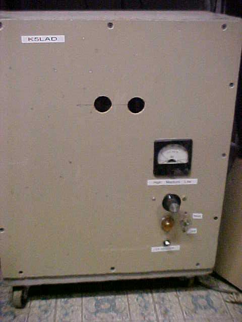
A view of the front of the power supply box which shows the 250 volt AC meter which parallels the amber panel light. The two circles near the top were not meant to look like something spooky to scare away small children but instead, it provides a nice exit for the air blown in by the fan in the rear. Even if you had extra long fingers, you can't get into anything that will burn or shock by reaching through those holes. I probably will eventually cover the holes with some type of screen wire. For now, however, I just don't allow any idiots into my hamshack who might try to insert a long screwdriver though a hole. |
 |
 |
 |
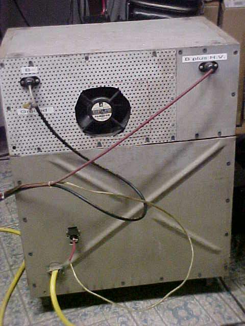
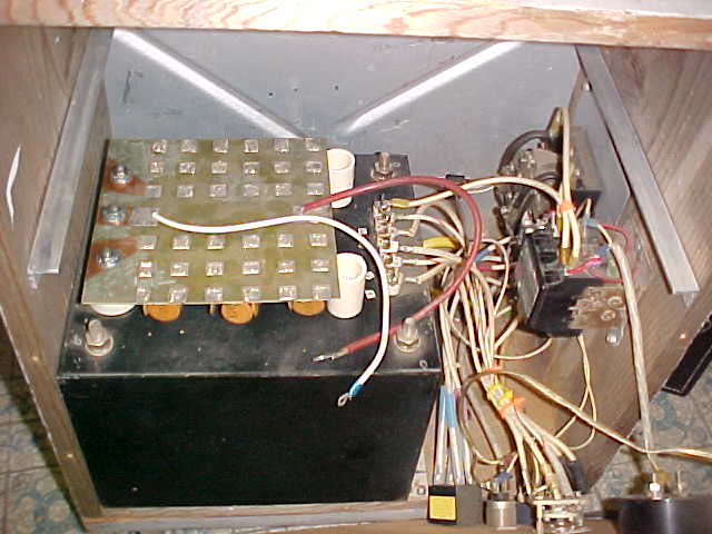
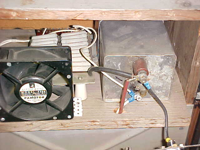
This is the back side of the box containing the power supply for the amplifier. It's not even close to being pretty but it works well. The fan is blowing directly across the bleeder resistor board for reasons previously mentioned. The yellow cable at the lower left is the 240 volt AC cable. The wire terminated in a plug just above that is the remote control cable. It comes from the H.V. switch on the amplifier's front panel. This allows remotely controlling of the power supply from the amplifier. |
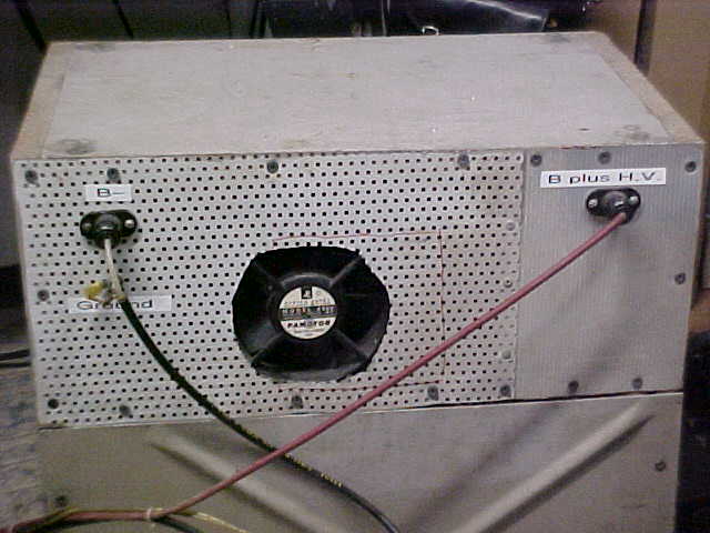
A closer look at the top of the power supply shows the cables which handle the high voltage. The cable on the left is made from a piece of RG-59U coax. The B- lead is 10 ohms above ground so the shield of the coax is grounded the the B- is above it. The red positive cable is high voltage cable. Although the B+ high voltage connector should be red, I never was able to run across a red Millen connector. It's pretty evident where the positive cable should go, however. |
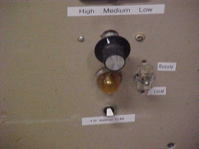
These controls are on the front panel of the power supply box. The knob switches various configurations of the high voltage transformer's primary. The amber light under it gives me a visual indication that the power supply is powered up. The switch under the light is an OFF/ON switch if desired but it's actually the 15 amp double circuit breaker described earlier. On the right side is a DPDT center-off toggle switch. In the upper (Remote) position, the supply is controlled by the H.V. switch on the amplifier, in the (Local) position, the supply can be powered up with a flip of the switch. In the center position, the supply cannot be powered up and this is the only safe position when changing the position of the knob controlling the primary taps. |
|
 |
|
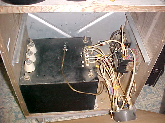
Not a particularly pretty sight but this shows the front panel off the power supply box. The two relays used for controlling the supply on remotely and in the slow-step-start control are shown on the right side. The power supply box is quite heavy, due to the potted high voltage transformer used. The box is 1/2" wood on the top, bottom, and sides, 1/4" Masonite board for the front panel, and aluminum pieces for the rear panel. The whole box is mounted on 4 swivel castors to allow it to be rolled around or moved out of the way. |
This picture, also with the front panel pulled down, shows the diode string board solidly mounted on the transformer's insulators. Note the two aluminum angle brackets mounted above the transformer and relay area. These brackets hold another piece of wood where are mounted the bleeder resistor board and the filter capacitor. The filter capacitor is a rectangular oil-filled 16 mfd at 5000 volts. It is 3 1/2" high by 4 1/2" wide by 9 1/4" long. It is mounted with the 4 1/2" x 9 1/4" down. |
This picture shows the piece of wood previously mentioned. Ugly, I reckon, but once any work is done on it, it is completely protected and any danger to a user is out of reach. The use of wood was not an accident since I wanted a high degree of insulation. You're looking at the back side of the board and even though the capacitor terminals hold the full high voltage charge of the power supply, the back is always on the box when I have it plugged in. I have considered rebuilding the complete power supply box and making it pretty and a work of art like I see in the magazine and handbook articles. So far, I've been able to say, "Nah, it just works too well the way it is. Leave well enough alone." ..... and I do. |
NOTE: At one time, I sat down and created a Troubleshooting Chart for my 4-1000A amplifier. It might not be useful to others but I will include it as part of my documentation package. Click here to display this Troubleshooting Chart.
.================================================================================================================
Written August 13, 2008
Updated 01/18/09 01:41 AM
Page visited 4767 times